Controlling Operation and Outputting Data with the Sensor's Standard Parallel Connection
248
FQ2 User’s Manual
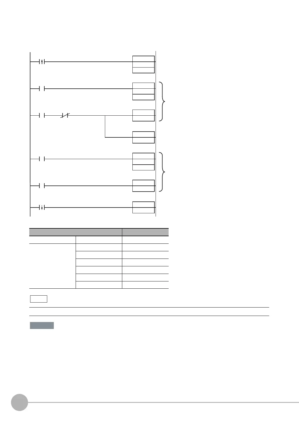
Sample Ladder Program
This sample program is used to change the scene when the input mode is set to Expanded Mode. The scene
changes to scene 1 when W0.00 turns ON.
• I/O Signal Allocations
If the cycle time is too long, the PLC may not be able to detect when the BUSY signal is ON. If necessary, turn
OFF W0.00 after a suitable time elapses.
Signal Address
Output signals OUT1 (BUSY signal) CIO 0.01
Input signals IN0 CIO 1.08
IN1 CIO 1.09
IN2 CIO 1.10
IN3 CIO 1.11
IN4 CIO 1.12
IN5 CIO 1.15
The BUSY signal will be ON while the scene it being changed.
MOV
#1100
Q:1
TMHH
0000
#5
TMHH
0001
#2
SET
IN5
RSET
IN5
SET
W0.01
W0.00
T0000
IN5
OUT1
BUSY
W0.00
RSET
W0.00
T0001
BUSY
Scene change
bit
Scene change
bit
When the scene change bit (W0.00) turns ON,
the scene number is input to IN0 to IN3 and
IN4 is turned ON.
If the BUSY signal is OFF 5 ms after the
scene number is input, the trigger to change
the scene (IN5) is turned ON.
The trigger to change the scene (IN5) is kept
ON for 2 ms and then turned OFF.
When the BUSY signal turns OFF to indicate
that the scene has been changed, processing
after changing the scene is performed (W0.01
turned ON).

 Loading...


