Controlling Operation and Outputting Data with a Parallel Interface Sensor Data Unit
FQ2 User’s Manual
261
8
Controlling Operation and Outputting Data
with a Parallel Connection
Data Output Timing
● Output Sequence
If both parallel judgement output and parallel data output are performed at the same time, parallel judgement
output will be performed first followed by parallel data output.
Example: Parallel Judgement Output of D0 to D15 and Parallel Data Output of Data 0
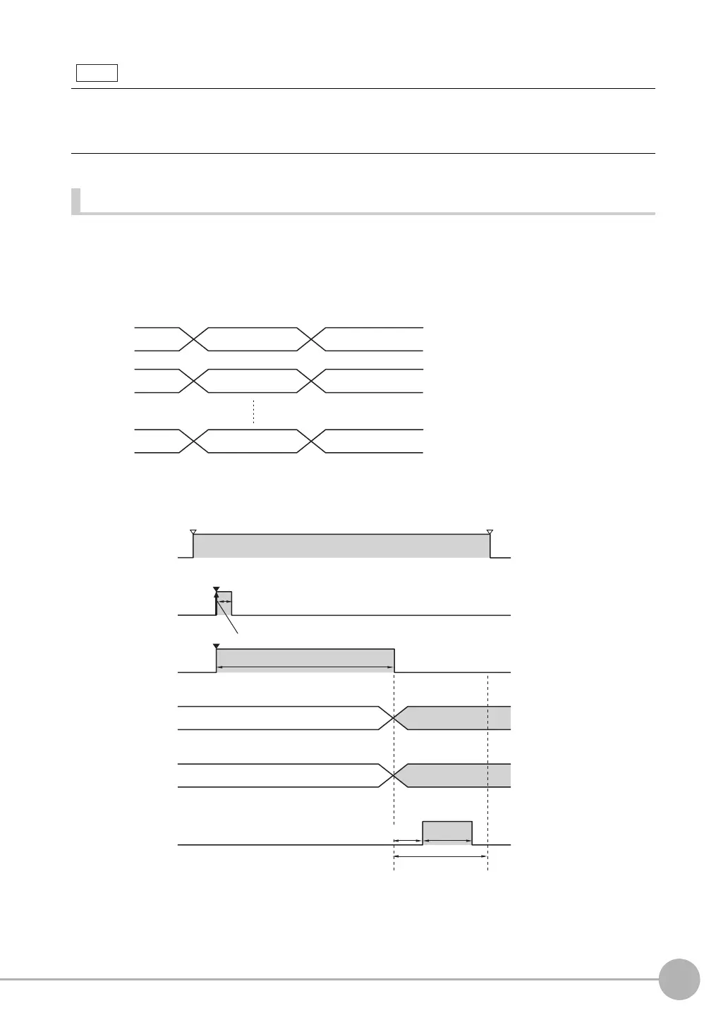
● Timing Chart
The following timing chart shows the data output timing for parallel judgement outputs.
The data that is output to the OR and D signals after a measurement is held until the next measurement is per-
formed. The values will continue to be output even after all measurements have been completed.
However, if you set the output timing of the OR signal to [One-shot output] in the [Output mode] parameter, the OR
signal will turn OFF after the specified output time has elapsed.
Parallel judgement
output D0
Parallel data output
(data 0)
Parallel judgement
output D1
Parallel data output
(data 0)
Parallel judgement
output D15
Parallel data output
(data 0)
D0
D1
D15
Overall judgement
Parallel
judgement output
(D0 to D15)
BUSY signal
OFF
ON
OR signal
D signals
OFF
ON
RUN signal
OFF
ON
TRIG signal
OFF
ON
GATE signal
OFF
ON
Measurements executed.
GATE
ON delay
Output time
Output period
Run Mode entered.
ON for 1 ms min.
Setup Mode entered.
The FQ2 starts measurements when it detects the rising edge
(OFF to ON transition) of the TRIG signal.

 Loading...


