Controlling Operation and Outputting Data with a Parallel Interface Sensor Data Unit
FQ2 User’s Manual
277
8
Controlling Operation and Outputting Data
with a Parallel Connection
Input Signals
Teaching
This command uses the image that is currently being input to execute teaching for all of the registered
inspection items (except for Edge Pitch).
Parameters
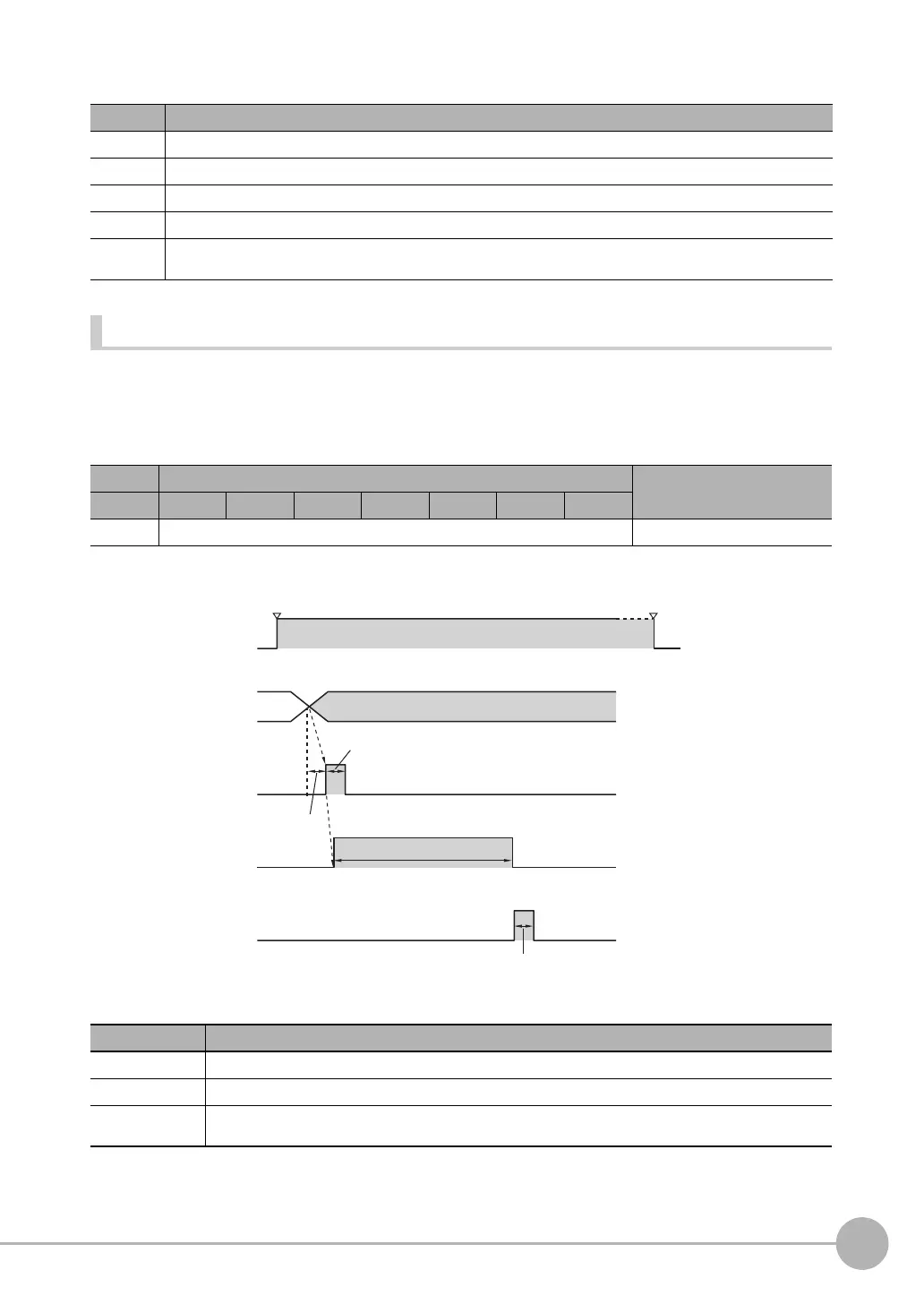
Timing Chart
Output Signals
Signal Function
IN0 to IN2 Turn OFF.
IN3 Turn ON.
IN4 and IN5 Turn OFF.
IN6 Turn ON.
IN7 This signal is the trigger for executing re-registration of the model and reference color. Set the IN0 to IN6 signals, wait for
at least 5 ms, and then turn ON the IN7 signal. The BUSY signal will be ON while the command is being executed.
Execution Command Input example
IN7 IN6 IN5 IN4 IN3 IN2 IN1 IN0
1 1001001 11001001
Signal Function
RUN This signal is ON while the Sensor is in Run Mode. It will be OFF in Setup Mode.
BUSY This signal is ON while teaching is being executed.
ACK When the command has been completed normally, this signal is turned ON for the time that is set for the ACK
output time.
0
IN7 signal
OFF
ON
OFF
ON
OFF
ON
RUN signal
OFF
ON
IN0 to IN6 signals
Run Mode entered. Setup Mode entered.
BUSY signal
Command execution
1001001
Allow 5 ms min.
and then turn ON IN7.
ON for 1 ms min.
ACK signal
ACK output time

 Loading...


