Controlling Operation and Outputting Data with a Parallel Interface Sensor Data Unit
278
FQ2 User’s Manual
Input Signals
Clearing the OR and D Signals
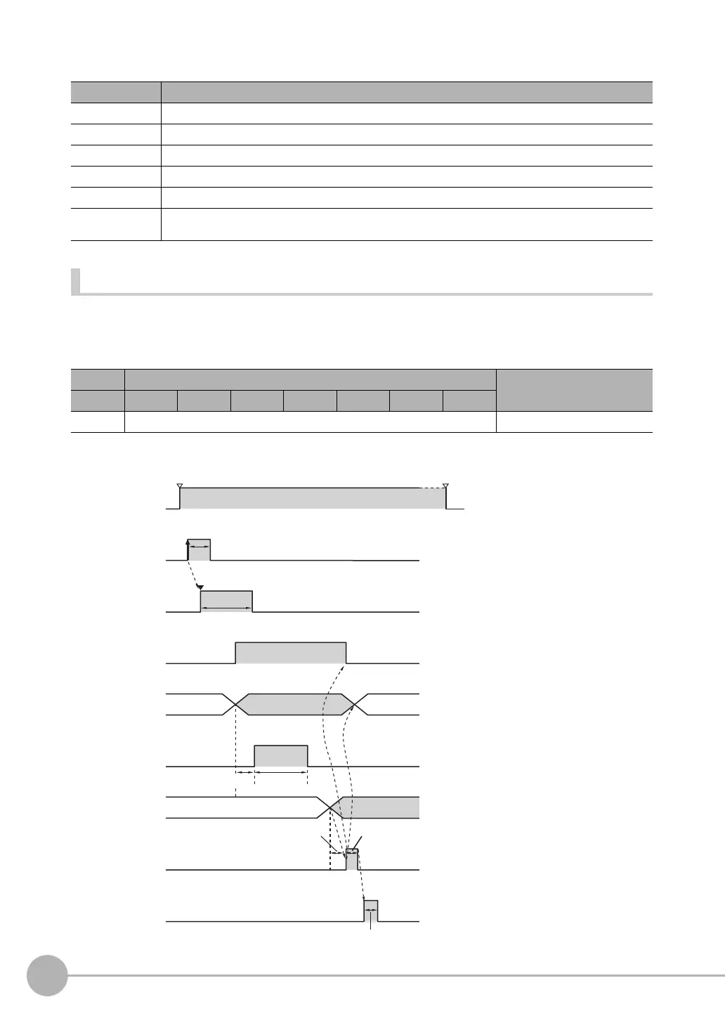
This command clears the OR signal and D signals.
Parameters
Timing Chart
Signal Function
IN0 Turn ON.
IN1 and IN2 Turn OFF.
IN3 Turn ON.
IN4 and IN5 Turn OFF.
IN6 Turn ON.
IN7 This signal is the trigger for executing teaching. Set the IN0 to IN6 signals, wait for at least 5 ms, and then turn
ON the IN7 signal. The BUSY signal will be ON while the command is being executed.
Execution Command Input example
IN7 IN6 IN5 IN4 IN3 IN2 IN1 IN0
1 1000010 11000010
ON for 1 ms min.
TRIG is input.
OR signal
BUSY signal
OFF
ON
OFF
ON
RUN signal
OFF
ON
TRIG signal
OFF
ON
Run Mode entered. Setup Mode entered.
D signals
Measurements executed.
GATE signal
OFF
ON
Output time
1000010
GATE ON delay
IN0 to IN6
signals
IN7 signal
OFF
ON
Data
0
ACK signal
OFF
ON
ACK output time
Allow 5 ms min.
and then turn ON IN7.
ON for 1 ms min.

 Loading...


