Servicing the 7x20 Controller
7420 Rear Panel
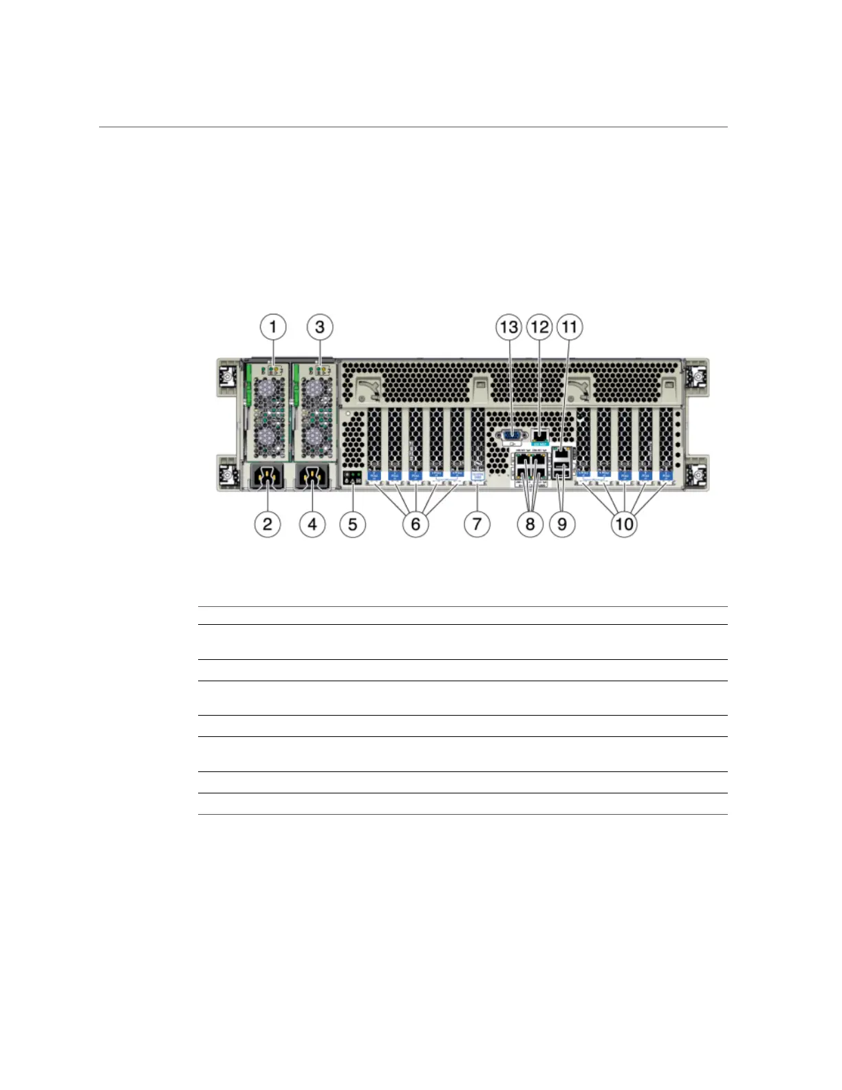
The following graphic shows the rear panel of the controller. Base configuration HBAs are not
depicted in this illustration.
FIGURE 38
7420 Controller Rear Panel
Figure Legend Figure Legend
1 Power supply unit 0 status LEDs OK: green Power
Supply Fail: amber AC OK: green
8 Network (NET) 10/100/1000 ports: NET0-NET3
2 Power supply unit 0 AC inlet 9 USB 2.0 ports
3 Power supply unit 1 status LEDs OK: green Power
Supply Fail: amber AC OK: green
10 PCIe slots 5-9
4 Power supply unit 1 AC inlet 11 Network management (NET MGT) port
5 System status LEDs Power: green Attention: amber
Locate: white
12 Serial management (SER MGT) port
6 PCIe slots 0-4 13 DB-15 video connector
7 Cluster card slot
7420 Physical Specifications
The 3U chassis form factor dimensions are as follows:
Servicing the Hardware 159
 Loading...