Servicing the ZS4-4 Controller
Each memory riser card contains twelve DIMM slots, four DDR3 channels, and two memory
buffer ASICs. Each each memory buffer has two channels (A and B) and links to three
DIMM slots per channel. Each memory buffer is connected to the processor's built-in memory
controller by an SMI-2 link.
DIMM names in appliance logs and the Maintenance > Hardware view are displayed with the
full name, such as /SYS/MB/P0/D7.
For more information about memory layout and procedures for replacing DIMMs, see
“Replacing the ZS4-4 Hardware” on page 58.
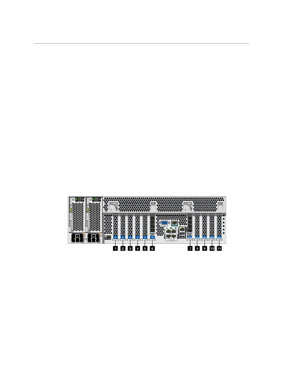
ZS4-4 PCIe I/O Slot Numbering
The ZS4-4 base configuration contains the following PCIe cards:
■
One 8-port SAS-2 internal HBA (slot 2)
■
Two 4-port (4x4) SAS-2 external HBAs (slot 6 and slot 7)
■
One cluster interface card (slot 4)
The following figure shows the PCIe I/O slot numbers.
FIGURE 8
ZS4-4 PCIe I/O Slot Numbers
Additional client-facing cards can be installed in the remaining PCIe slots. See “ZS4-4 PCIe
Slot Order” on page 51.
ZS4-4 PCIe Slot Order
Install optional PCIe cards in the following order:
Servicing the Hardware 51
 Loading...