Mixed Signal Operation (Option R&S RTC-B1)
R&S
®
RTC1000
110User Manual 1335.7352.02 ─ 02
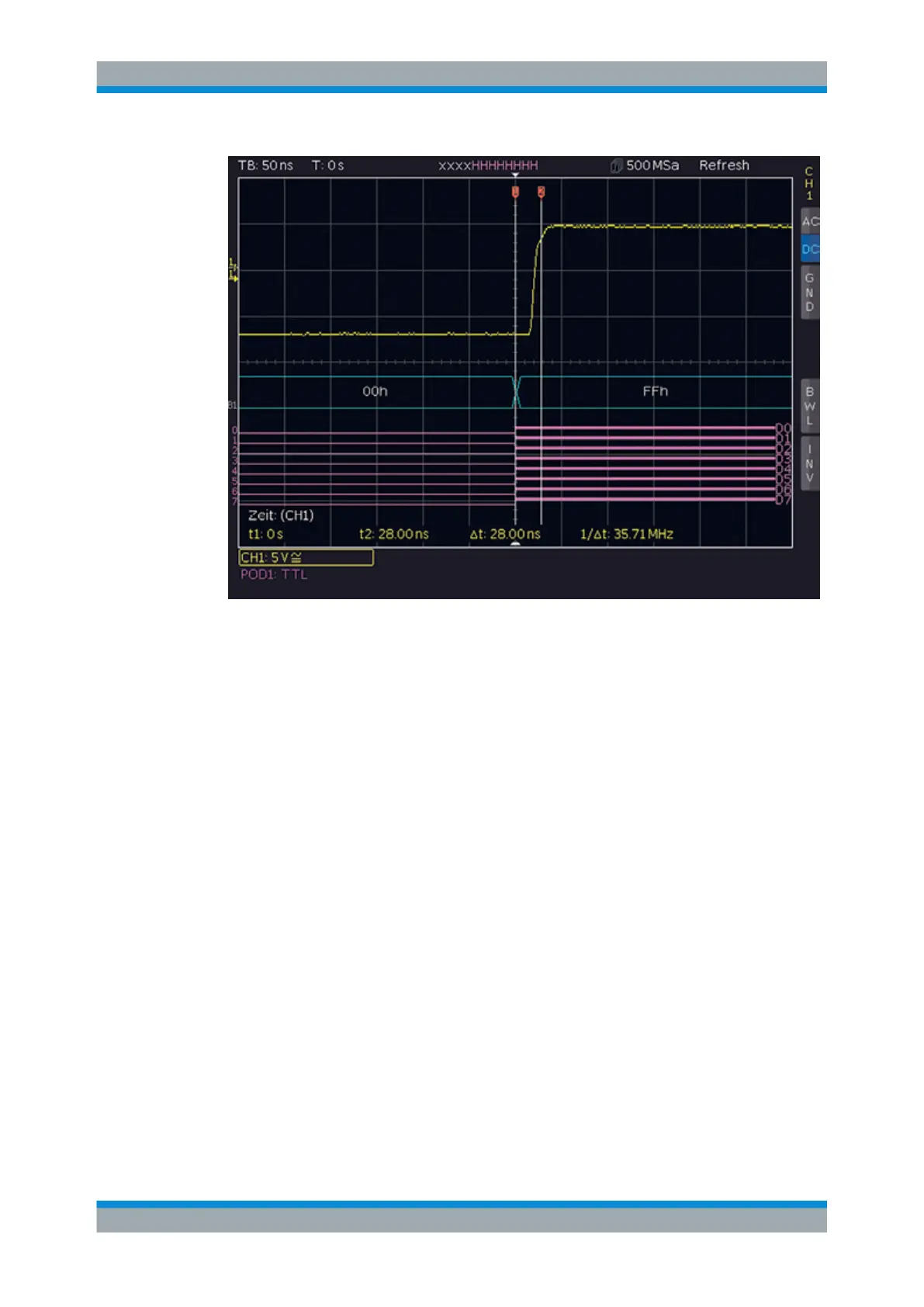
Figure 9-3: Bit DAC signal change
9.2 Logic Trigger for Digital Input
To trigger on logic channels, you can use the logic trigger, see Chapter 5.5, "Logic
Trigger", on page 52.
9.3 Cursor Measurements for Logic Channels
If the logic channels active, you can determine several parameters using cursor mea-
surements (CURSOR MEASURE key).
The following measurement types are available:
●
TIME:
The display shows the time position of both cursors relative to the trigger time, the
time difference between the two positions and the resulting frequency.
●
RATIO X:
Three cursors are used to display a time ratio between the first two cursors plus the
first and third cursor. The results are shown in floating point format, in percent, in
degrees and in radians.
●
V-MARKER:
Cursor Measurements for Logic Channels

 Loading...


