Serial Bus Analysis
R&S
®
RTC1000
135User Manual 1335.7352.02 ─ 02
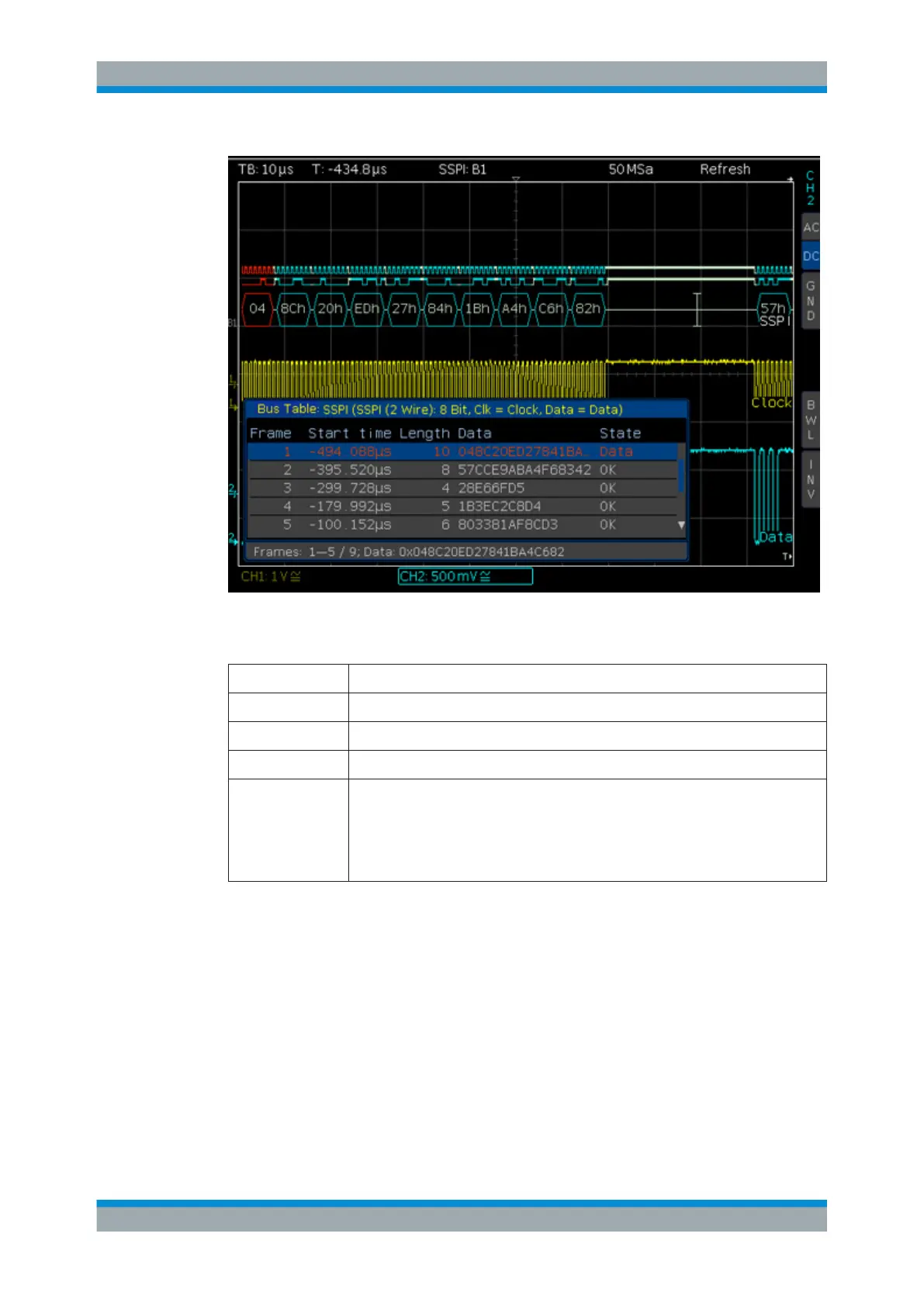
Figure 11-9: Example of an SSPI bus table
Table 11-2: Content of the SPI/SSPI bus table
Column Description
"Start Time" Time of frame start in relation to the trigger point
"Length" Number of words in the frame
"Data" Values of the data words
"State"
Frame Status:
●
"OK" = frame is valid
●
"DATA" = during acquisition start/end only the frame start / frame end has been
decoded; currently no data available
●
"INS" = the frame is not contained in the acquisition; the acquired part of the
frame is valid.
11.5 UART/RS-232 BUS (Option R&S RTC-K2)
For UART/RS-232 bus trigger and decoding, you need the R&S RTC-K2 option.
The UART bus (Universal Asynchronous Receiver Transmitter) is a general bus sys-
tem and the base for many protocols. One example is the RS-232 protocol. It consists
of a frame with a start bit, 5 to 9 data bits, one parity bit and a stop bit. The stop bit can
assume the single length, or 1.5 or twice the length of a normal bit.
UART/RS-232 BUS (Option R&S RTC-K2)

 Loading...


