Trigger
R&S
®
RTC1000
51User Manual 1335.7352.02 ─ 02
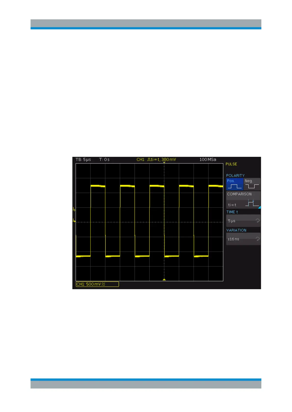
5.4 Pulse Trigger
The pulse trigger finds specific pulse widths of positive or negative pulses or on pulse
width ranges. If a pulse on the trigger source fulfills the trigger condition, the oscillo-
scope triggers on the trailing slope. For a positive pulse, it triggers on the falling slope,
and for a negative pulse on a rising slope.
1. Select TYPE > "PULSE".
2. To set the polarity, press the SLOPE key repeatedly.
The selected polarity is shown above the key, and on top of the grid in the display.
3. To set the trigger level, turn the LEVEL knob.
4. Select FILTER.
The filter settings define the pulse direction and length for the pulse trigger:
TIME t, TIME t
1
,TIME t
2
, VARIATION
Set the reference pulse length depending on the selected comparison.
The comparison time can be set between 16 ns to 10s. For values up to 1 ms, the res-
olution is 2 ns. and for any value greater than 1 ms the resolution is 1 μs.
The deviation can be set from ±8 ns up to 657.5 μs with a resolution of 8 ns.
Pulse Trigger

 Loading...


