Getting Started
R&S
®
RTC1000
17User Manual 1335.7352.02 ─ 02
Logic probe (9)
The connector for logic channels can be used if the Mixed Signal Option R&S RTC-B1
is installed. The option provides a logical probe with 8 digital channels (D0 to D7).
The maximum input voltage is 40 V (peak) at 100 kΩ input impedance. The maximum
input frequency for a signal with the minimum input voltage swing and medium hystere-
sis of 800 mV (Vpp) is 300 MHz.
Risk of instrument damage
Use the connector for the active logic probe exclusively for the logic probe R&S RT-
ZL03, which is delivered with option R&S RTC-B1. Connecting other probe types can
demolish the input.
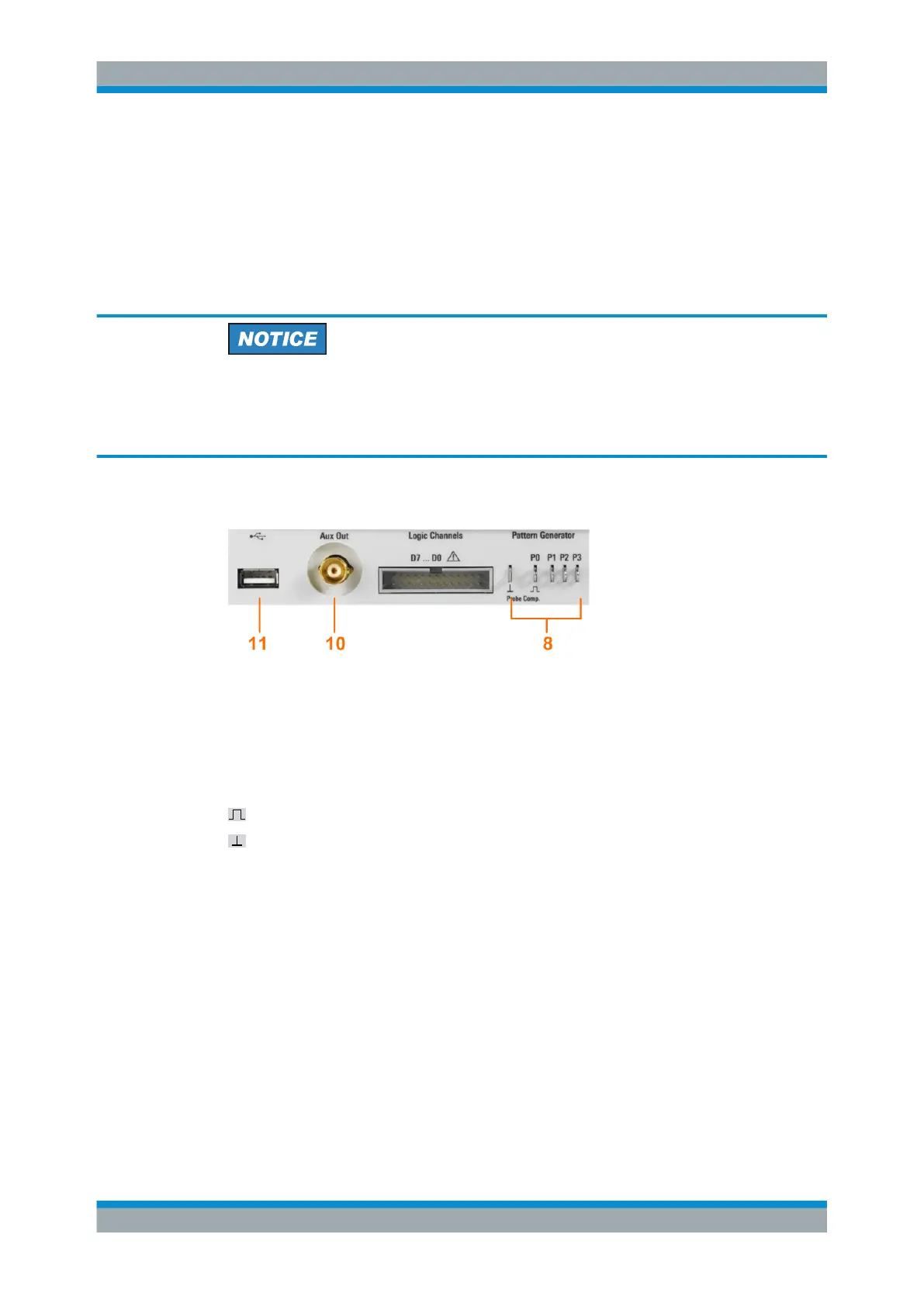
2.2.1.2 Other Connectors on the Front Panel
PATTERN GENERATOR (8)
Connectors for the pattern generator P0, P1, P2, P3.
PROBE COMP. (8)
Probe compensation terminal to support adjustment of passive probes to the oscillo-
scope channel.
Square wave signal for probe compensation.
Ground connector for probes.
AUX OUT (10)
Multi-purpose BNC output that can function as pass/fail and trigger output, output for
component testing, and as function generator output (with option R&S RTC-B6).
USB type A (11)
USB 2.0 type A interface to connect a USB flash drive for storing and reloading instru-
ment settings and measurement data, and to update the firmware.
2.2.2 Rear Panel
Figure 2-2 shows the rear panel of the R&S RTC1000 with its connectors.
Instrument Tour

 Loading...


