SERVICE TOOLS
SM 4-9 A251/A252
Service
Tables
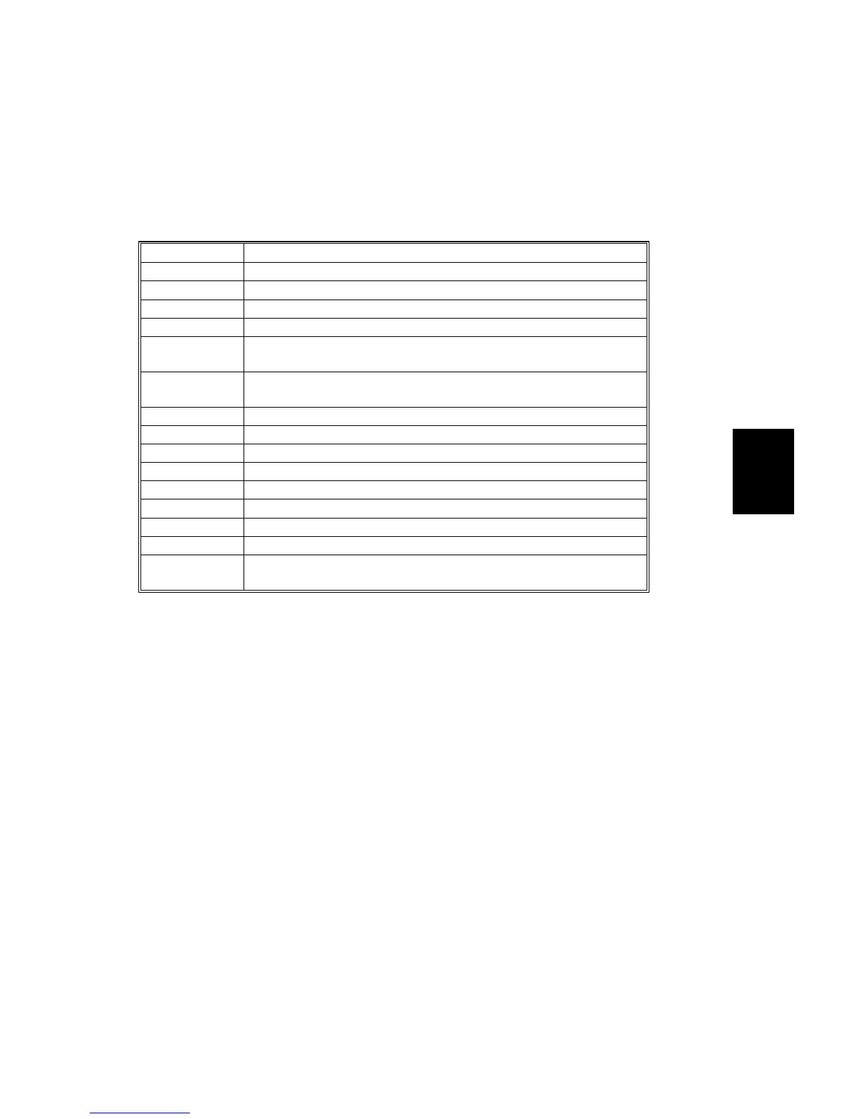
4.3.2 INPUT/OUTPUT CHECK MODE
Input Check Mode Table
The on/off status of the selected electrical component is displayed in the paper
length indicator (“ON” or “OFF” is displayed). If a program number not used is
selected, “NOT” is displayed.
Program No. Sensor/Switch/Signal
-1 Registration Sensor
-2 Exit Sensor
-3 Original Registration Sensor
-4 Entrance Sensor
-5
Main Motor LOC Signal
(Status is “ON” when the main motor is normally rotating.)
-6
Door Switch
(Status is “ON” when the door is open.)
-7 Original Entrance Sensor (A252 copier only)
-8 Original Rear Sensor (A252 copier only)
-9 Not Used
-10 R/F Leading Edge Sensor
-11 Roll Feeder Door Switch
-12 Right Cutter Switch
-13 Left Cutter Switch
-14 Paper End Sensor
-16
Exit Cover Open
(Status is “ON” when the door is open.)
 Loading...