Mechanical mounting
6.3 Installing/removing the rotor
SIMOTICS M-1FE2 built-in motors
100 Hardware Installation Manual, 04/2020, A5E50074509B AA
Procedure during mounting
Danger caused by hot/cold surfaces
During mounting, the components are very hot or very cold and can cause burns or frost
bite.
• Do not touch any components with unprotected hands.
• Wear heat-resistant gloves, safety goggles and closed work clothes.
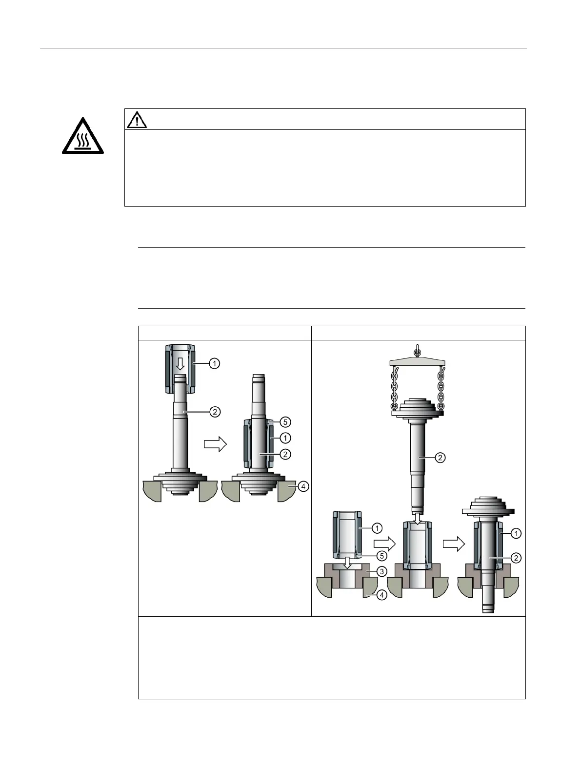
1. Select joining process A or B
Note
Different shape
The spindle shaft is supplied by the spindle manufacturer. The shape of the spindle shaft
may differ from the illustration.
B Joining the spindle shaft
1 Rotor core
2 Spindle shaft
3 Mounting device
1)
4 Rigid support
5 Oil connection hole
1)
For rotors with permanent magnets made of non-magnetic material
 Loading...


