3 Mounting and Commissioning
460
7SD5 Manual
C53000-G1176-C169-1
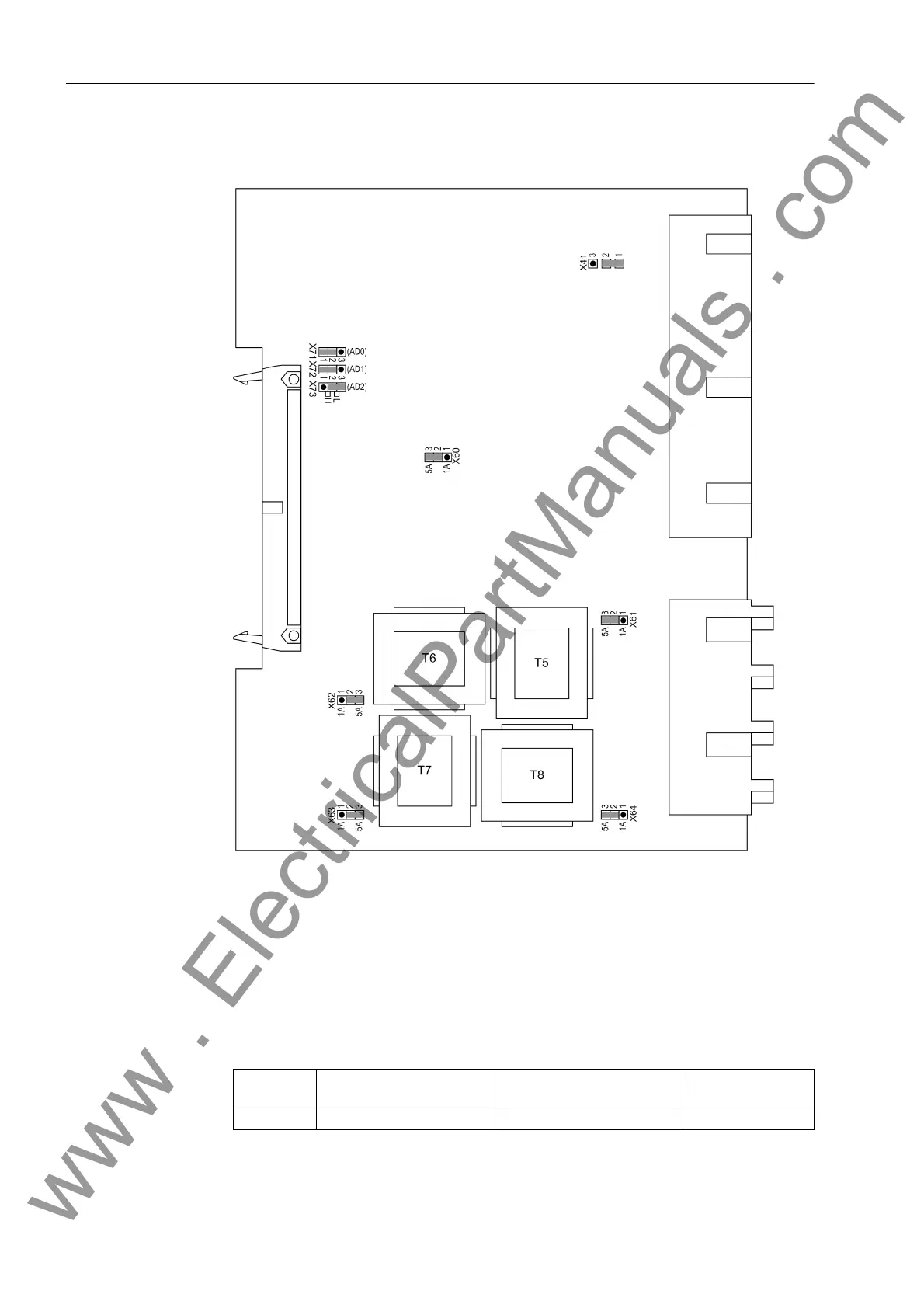
Board C-I/O-2 The layout of the PCB for the C-I/O-2 board is shown in Figure 3-7.
Figure 3-7 Input/output board C–I/O-2 with representation of jumper settings required for
checking configuration settings
The contact of the relay for the binary output BO13 can be configured as NO or NC
contact (see also General Diagrams in Appendix A, Section A.2):
with housing size
1
/
2
: No. 3 in Figure 3-3, slot 33,
with housing size
1
/
1
: No. 3 in Figure 3-4, slot 33 right.
Table 3-8 Jumper setting for contact type of binary output BO13
Jumper Open in Quiescent State
(NO)
Closed in Quiescent State
(NC)
Factory Setting
X41 1-2 2-3 1-2
www . ElectricalPartManuals . com
 Loading...


