16. Electrical Equipment
16-5
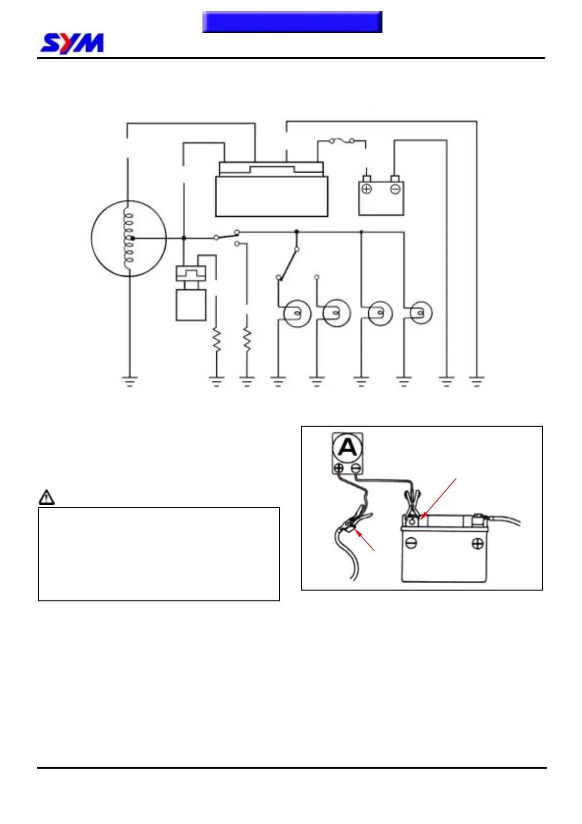
Charging System
Wire Diagram
Current Leakage Inspection
Turn the main switch to OFF position, and remove
the negative cable terminal (-) from the battery.
Connect an ammeter between the negative cable
terminal and the battery negative terminal (as
shown on left diagram).
Caution
● In the current leakage test, set the current
range at larger scale, then gradually
decrease to the lower scale as the test
process goes to avoid possible damage to
the ammeter and the fuse.
● Do not turn the main switch to ON position
during test.
If the leaked current exceeds the specified value, it
may indicate a short-circuit.
Allowable current leakage: Less than 1mA
Disconnect each cable one by one and take
measurement of the current of each cable to
locate the short circuit.
Alternator
Automatic
by-starter
oltage regulato
/ Rectifier
Fuse (7A)
Battery
G
Y
W
R
5W 12Ω (HU05U)
5W 10.2Ω (HU10U/W)
30W 5.9Ω
G/B
P
Battery (-) terminal
Ground
wire
W-White
Y-Yellow
G-Green
R-Red
B-Black
P-Pink
To this chapter contents

 Loading...