10065–01
32145
–20
0
20 40 60
80
100
0.1
0.2
0.3
0.5
1
2
3
5
10
20
30
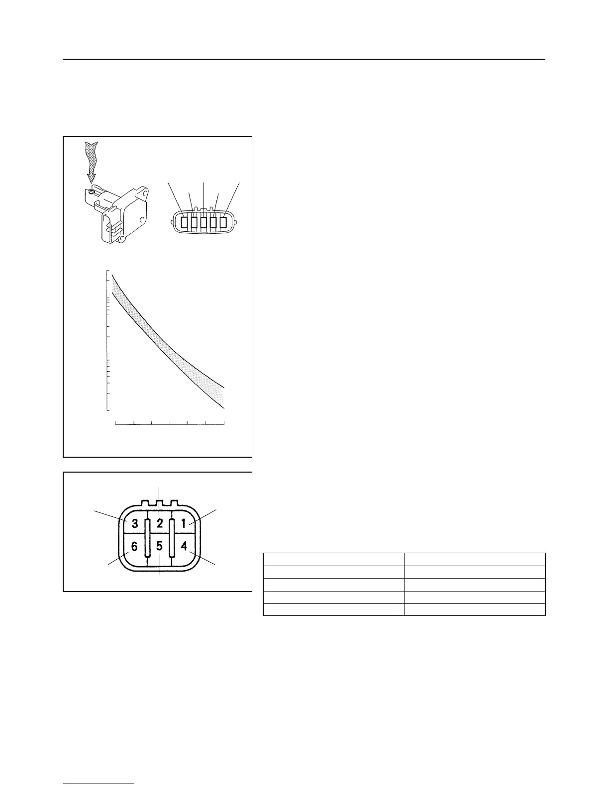
TEMPERATUREC(F)
RESISTANCE kΩ
(–4) (32) (80) (140)(104) (212)(176)
Air
E2
THA
VG
E2G
+B
A50378
A60485
VPA2
EP2
VCP2
VCP1
EP1
VPA1
10–8
–ENGINE CONTROL SYSTEM SFI SYSTEM (1MZ–FE)
1438Author: Date:
2002 CAMRY REPAIR MANUAL (RM881U)
INSPECTION
1. INTAKE AIR FLOW METER SUB–ASSY
(a) Output voltage inspection.
(1) Apply battery voltage across terminals 1 (+B) and 2
(E2G).
(2) Using a voltmeter, connect the positive (+) tester
probe to terminal VG, and negative (–) tester probe
to terminal E2G.
(3) Blow air into the MAF meter, and check that the volt-
age fluctuates.
(b) Resistance inspection.
(1) Using an ohmmeter, measure the resistance be-
tween terminals 4 (THA) and 5 (E2).
Resistance:
–20C (–4 F) 13.6 – 18.4 kΩ
20C (68F) 2.21 – 2.69 kΩ
60C (140F) 0.493 – 0.667 kΩ
2. ACCELERATOR PEDAL ASSY
(a) Resistance inspection
(1) Using an ohmmeter, measure the resistance be-
tween terminals.
Resistance:
Terminal Resistance
2 (VPA2) ⇔ 3 (EP1) 5.0 kΩ or less
5 (VPA1) ⇔ 1 (EP2) 5.0 kΩ or less
6 (VCP1) ⇔ 3 (EP1) 2.25 – 4.75 kΩ
4 (VCP2) ⇔ 1 (EP2) 2.25 – 4.75 kΩ

 Loading...