Z17008
C
SHORT
1
2
B
1
2
1
2
A
Fig. 5
Z17009
Fig. 6
Sensor
C
B
A
ECU
1
2
1
2
2
1
Z17808
Fig. 7
Sensor
B2
A
11 1
C
B1
1
ECU
2
22
2
01–34
–INTRODUCTION HOW TO TROUBLESHOOT ECU CONTROLLED
SYSTEMS
34Author: Date:
2002 CAMRY REPAIR MANUAL (RM881U)
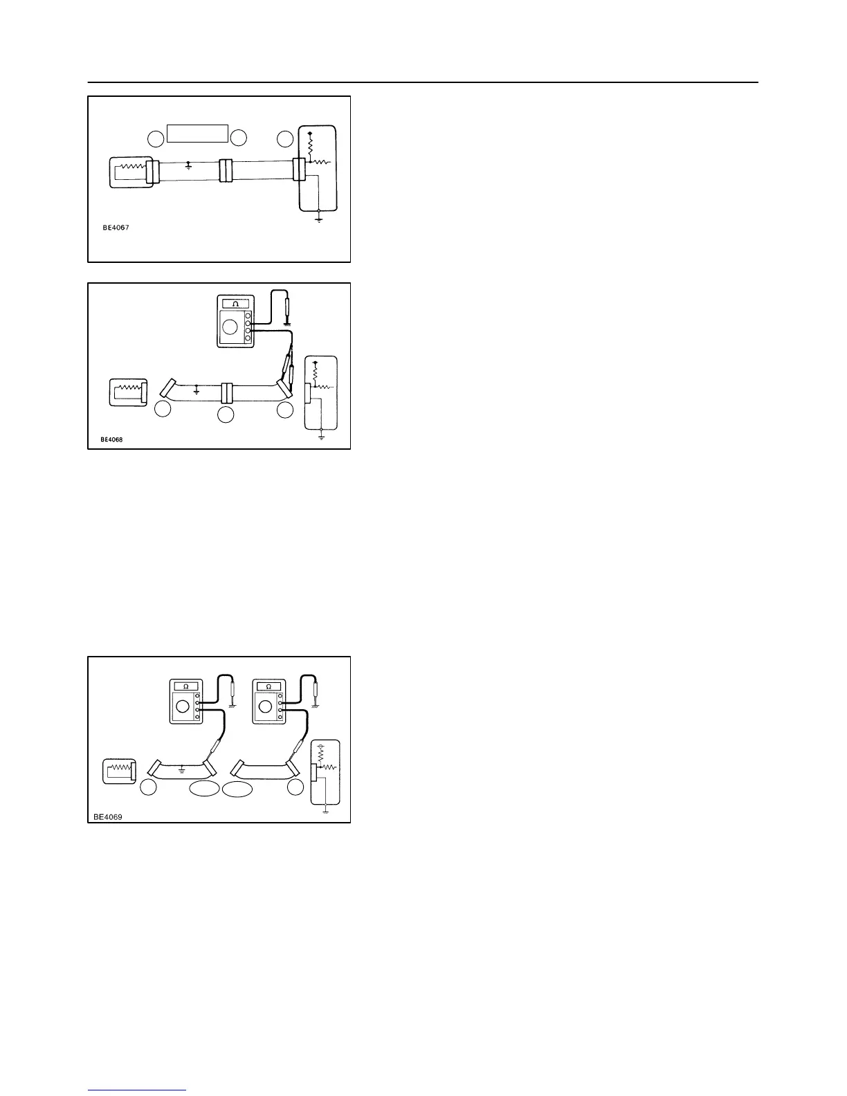
3. CHECK SHORT CIRCUIT
(a) If the wire harness is ground shorted as in Fig. 5, locate
the section by conducting a ”continuity check with the
body ground”.
(b) Check the continuity with the body ground.
(1) Disconnect connectors ”A” and ”C” and measure
the resistance between terminal 1 and 2 of connec-
tor ”A” and the body ground.
Resistance: 1 MΩ or higher
HINT:
Measure the resistance while lightly shaking the wire harness
vertically and horizontally.
In the case of Fig. 6:
Between terminal 1 of connector ”A” and body
ground → Continuity (short)
Between terminal 2 of connector ”A” and body
ground → No continuity
Therefore, it is found out that there is a short circuit
between terminal 1 of connector ”A” and terminal 1
of connector ”C”.
(2) Disconnect connector ”B” and measure the resis-
tance between terminal 1 of connector ”A” and the
body ground, and terminal 1 of connector ”B2” and
the body ground.
In the case of Fig. 7:
Between terminal 1 of connector ”A” and body
ground → No continuity
Between terminal 1 of connector ”B2” and body
ground → Continuity (short)
Therefore, it is found out that there is a short circuit
between terminal 1 of connector ”B2” and terminal
1 of connector ”C”.

 Loading...