Z17005
Fig. 2
Sensor
C
B
A
ECU
1
2
1
2
2
1
B04722
Fig. 3
Sensor
B2
A
1
2
1
2
2
1
C
B1
1
2
ECU
Z17007
Fig. 4
Sensor
C
B
A
1
2
1
2
2
1
5V
5V
0V
–INTRODUCTION HOW TO TROUBLESHOOT ECU CONTROLLED
SYSTEMS
01–33
33Author: Date:
2002 CAMRY REPAIR MANUAL (RM881U)
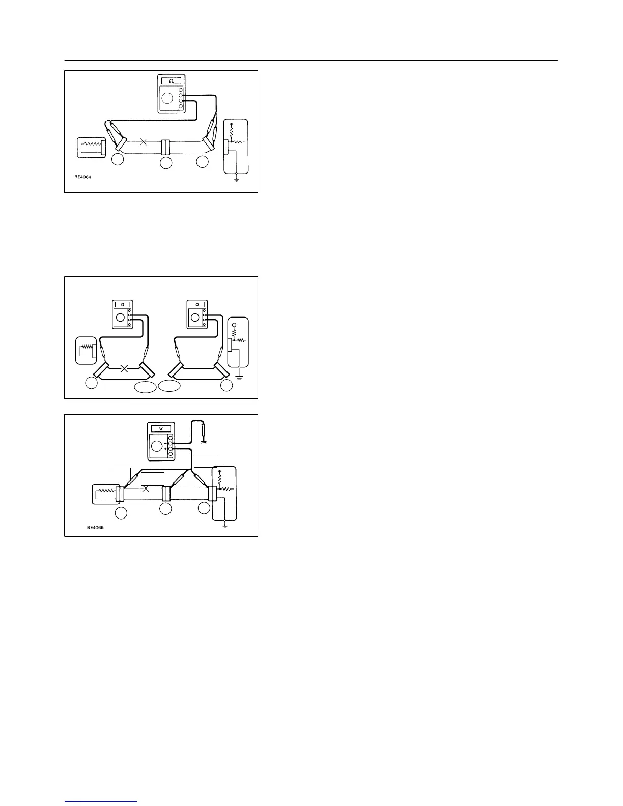
(b) Check the continuity.
(1) Disconnect connectors ”A” and ”C” and measure
the resistance between them.
Resistance: 1 Ω or less
HINT:
Measure the resistance while lightly shaking the wire harness
vertically and horizontally.
In the case of Fig. 2:
Between terminal 1 of connector ”A” and terminal 1
of connector ”C” → No continuity (open)
Between terminal 2 of connector ”A” and terminal 2
of connector ”C” → Continuity
Therefore, it is found out that there is an open circuit
between terminal 1 of connector ”A” and terminal 1
of connector ”C”.
(2) Disconnect connector ”B” and measure the resis-
tance between the connectors.
In the case of Fig. 3:
Between terminal 1 of connector ”A” and terminal 1
of connector ”B1” → Continuity
Between terminal 1 of connector ”B2” and terminal
1 of connector ”C” → No continuity (open)
Therefore, it is found out that there is an open circuit
between terminal 1 of connector ”B2” and terminal
1 of connector ”C”.
(c) Check the voltage.
(1) In a circuit in which voltage is applied (to the ECU
connector terminal), an open circuit can be checked
by conducting a voltage check.
As shown in Fig. 4, with each connector still con-
nected, measure the voltage between the body
ground and terminal 1 of connector ”A” at the ECU
5 V output terminal, terminal 1 of connector ”B”, and
terminal 1 of connector ”C”, in that order.
(2) If the results are:
5 V: Between terminal 1 of connector ”a” and body
ground
5 v: between terminal 1 of connector ”b” and body
ground
0 v: between terminal 1 of connector ”c” and body
ground
Then it is found out that there is an open circuit in
the wire harness between terminal 1 of ”B” and ter-
minal 1 of ”C”.

 Loading...