13.2 Installing Wired Remote Sensors
Up to 10 remote sensor modules, installed in the monitored racks and connected to the cooling unit, provide control and
reference input to Vertiv™ Liebert® iCOM and building-management systems. Using remote, rack sensors combats cooling
problems related to recirculation air, uneven rack loading, and air distribution.
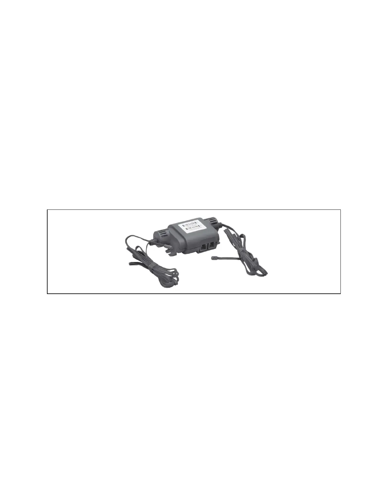
The sensor array consists of 2T sensors that each have two temperature probes on a 6 ft. (1.8 m) probe-connection cable,
Figure 13.3 below , and requires several steps to prepare, connect, and begin monitoring the racks:
• Set DIP switches in each sensor.
• Terminate final sensor on CANbus link.
• Install sensors on racks.
• Install CANbus cabling between sensors.
• Connect CANbus cable to the cooling unit.
• Configure the sensors in Liebert® iCOM™.
NOTE: The 2T sensor shown in Figure 13.3 below , may differ slightly for your system, depending on equipment
installed.
Figure 13.3 2T Sensor for Rack Monitoring
13.2.1 Setting DIP Switches and Labeling 2T Sensors
Tools required:
• Small, non-conductive tool to set switches.
• Small, Phillips head screw driver to open 2T housing.
Each sensor requires a unique address in the CANbus loop connected to the cooling unit. We recommend that you set the
DIP switch sensor number setting to correspond to the sensor’s location on the CANbus run. If settings are incorrect, the
control will not operate properly.
13 Vertiv™ Liebert® iCOM™ Hardware Installation
184
Vertiv™ Liebert® iCOM™Installer/User Guide
 Loading...


