U2U Network Requirements
The network must be private:
• Isolated from other network traffic/non-Liebert Thermal equipment.
• Switches connecting the units must be dedicated to Vertiv™ Liebert® iCOM™ communication only.
• Do not connect the U2U network to the building or IT network. If the U2U network experiences a failure, the
cooling units continue to operate independently.
Liebert® iCOM™ supports up to 64 nodes on the U2U network. The following are considered nodes:
• Input/output board (one in each cooling unit)
• Nine inch color touchscreen display or vNSA14-iCOM-H
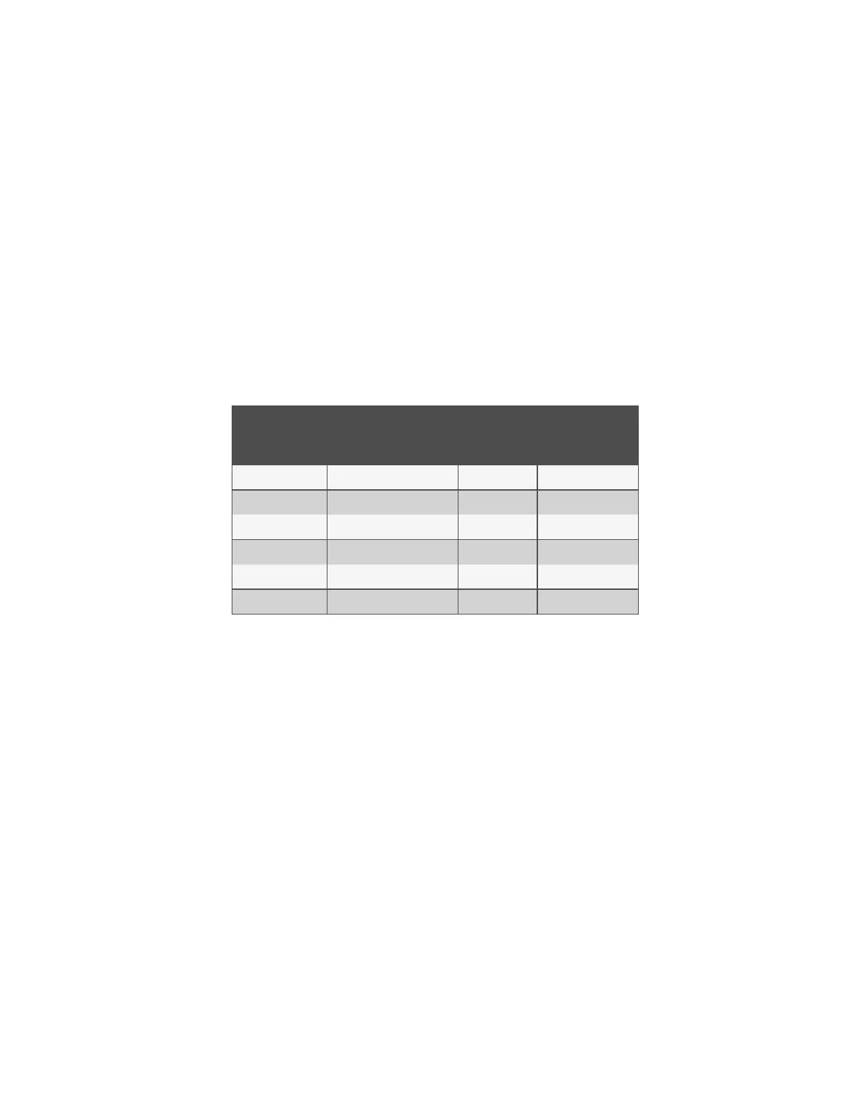
Of the 64 nodes, up to 32 may be cooling unit input/output boards connected as a group. Table 13.6 below , provides U2U
network configuration examples.
Configuration
Example
No. of Input/OutputBoards
(CoolingUnits)
No. of Wall
Mount
Displays
Private Switch
Required?
A 2 0 No
B 2 1 Yes
C 3 0 Yes
D 8 1 Yes
E 32 5 Yes
F 32 32 Yes
Table 13.6 Example Liebert® iCOM™ U2U Network Configurations
13.6.4 Wiring Cooling Units without Wall Mount Displays
NOTE: Cooling units are factory wired for stand alone operation. Do not connect the U2U network cabling before
setting the U2U network configuration/groups. Network communication conflicts and unreliable display readings will
result.
NOTE: Before you begin, refer to Preparing for U2U Group Set Up on page97 , andConfiguring U2U Network Settings
on page98 .
13 Vertiv™ Liebert® iCOM™ Hardware Installation
198
Vertiv™ Liebert® iCOM™Installer/User Guide
 Loading...


