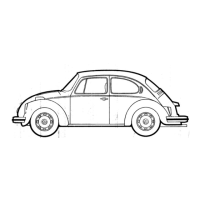
– Unlock locking lug -1- of relay carrier in -direction of arrow- and
take relay carrier off.
Installing:
Installation is performed in the reverse order of installation; when
doing this, note the following:
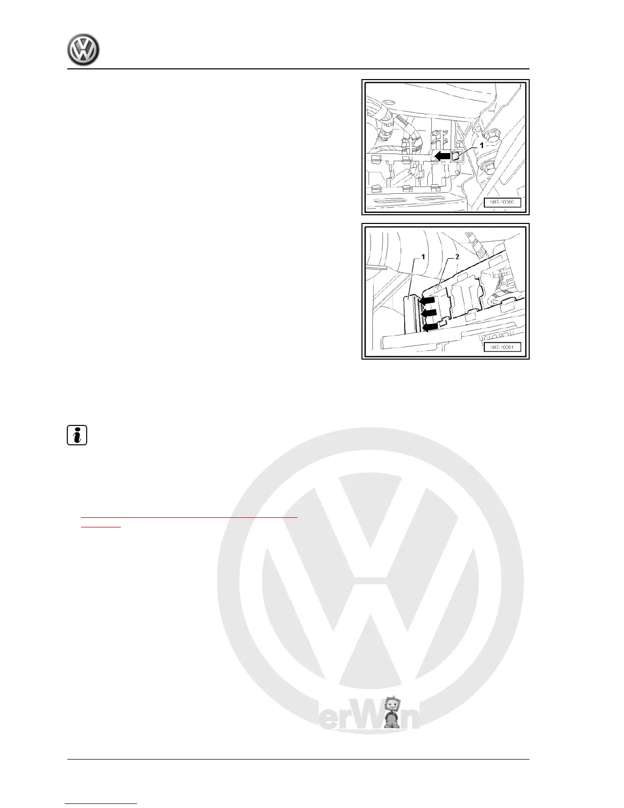
– Clip connectors into the relay carrier first.
– Fit relay carrier -2- into guide -1- and engage relay carrier.
3.2 Removing and installing relay carrier on
onboard supply control unit, on left of
dash panel
Note
♦
The onboard supply control unit -J519- and the relay carrier
attached to the onboard supply control unit, on left of dash
panel form one unit and cannot be separated.
♦
If the onboard supply control unit -J519- is to be replaced, first
carry out the procedure
⇒ “5.1.2 Coding onboard supply control unit J519 ”,
page 293 to read out the stored codes.
Removing:
– Switch off ignition and all electrical consumers and pull out
ignition key.
– Remove cover, footwell, on driver side ⇒ General body re‐
pairs, interior; Rep. Gr. 68 ; Compartments, covers and trim .
– Remove storage compartment on driver side ⇒ General body
repairs, interior; Rep. Gr. 68 ; Compartments, covers and trim .
Jetta 2005 ➤ , Bora 2006 ➤
Electrical System - Edition 05.2005
286 Rep. Gr.97 - Wiring
 Loading...