Manual R06-2016 19 / 172
ROTARY INDEXING TABLE CONTROLLER
EF2...B
COMPONENT DESCRIPTIONS | 3.1 Power Modules PM240-2
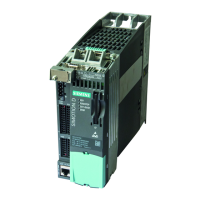
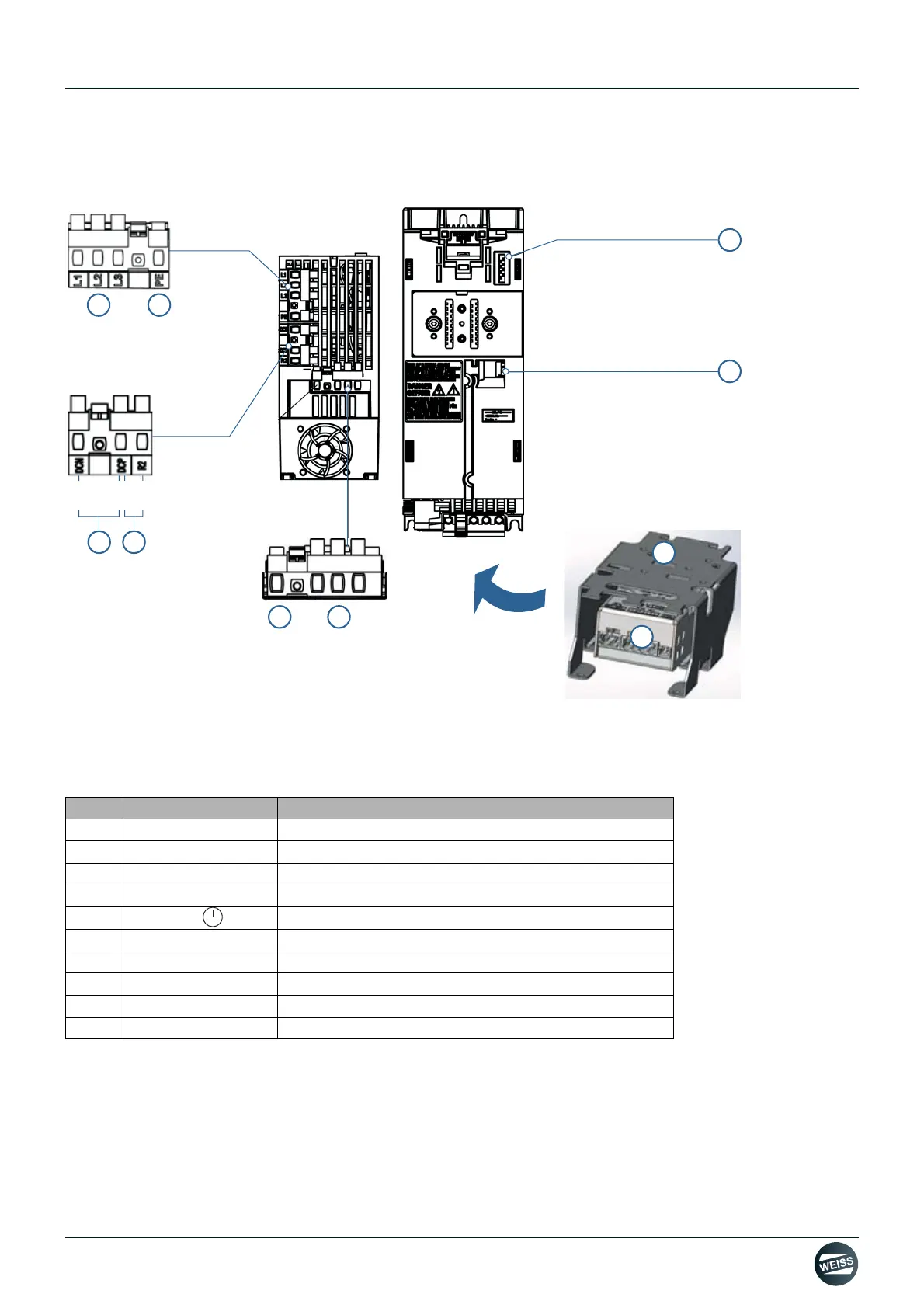
3.1.2 Power Module PM240-2; frame size FSA
Fig. 4: Interfaces of Power Module PM240-2; frame size FSA
The connections for mains, brake resistor and motor are detachable plug connections and are located on the
bottom side of the power module.
Refer to the device manual of the manufacturer for further information.
Pos.
Interface Description
(1) L / N
Power mains connection
(2) PE
Protective ground connection for the line supply cable
(3) DCN / DCP
DC bus negative / DC bus positive
(4) DCP / R2
Braking resistor connection
(5) PE
Protective ground connection for the motor cable
(6) U2 / V2 / W2
Motor connection
(7) PM-IF
Power module interface
(8) -
Brake relay connection
(9) - Shield terminal connection set
(10) - Brake Relay
 Loading...