Manual R06-201636 / 172
ROTARY INDEXING TABLE CONTROLLER EF2...B
FUNCTION AND SIGNAL DESCRIPTIONS | 4.2 Signal description of the software outputs
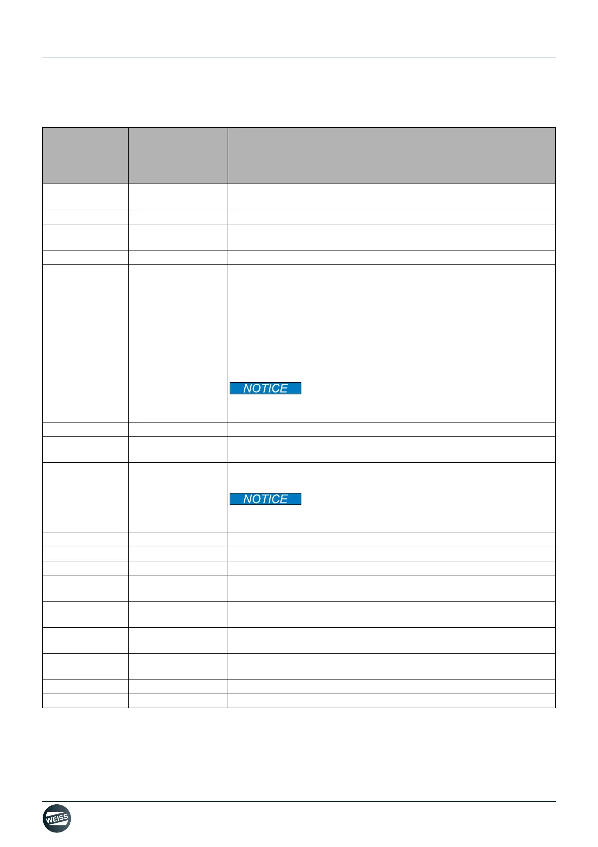
4.2 Signal description of the software outputs
Signal
Default
configuration
Outputs
PAD 256
Function
Ready for
switching on
Bit 12
All conditions are fulfilled. The release of the drive can be given via the
Enable input.
Enable active Bit 0 Displays that the drive is in the state Enable.
Ready to start Bit 1
This output signal indicates that the controller can accept a "Start" com-
mand or that the old command has been processed.
In operation Bit 13 The rotary indexing table carries out a rotating movement.
Indexer in
position
Bit 2
This output signal indicates that the rotary indexing table is in a locked
position. A position cam is mounted on the rotary indexing table for this
purpose. The signal from the position cam is sent to this output without
being changed (1:1).
If this output signal is HIGH again after the end of the cycle, then proces-
sing can be started because the rotary indexing table is no longer
moving. The motor of the rotary indexing table will however continue to
move as long as specified by the stop delay or stop ramp that was set, in
order to reach an optimal starting position for the next cycle.
If, however, this output signal is LOW, then processing
must be stopped immediately because the rotary indexing table has left
its position.
Stop selected Bit 3 Direct feedback from the Stop input.
Alarm timeout Bit 4
The rotary indexing table did not reach the next locking position within the
specified time.
Alarm position
run over
Bit 5
This output signal indicates that the position cam of the rotary indexing
table was overrun.
If this error message is received, then processing must
be stopped immediately because the rotary indexing table has left its
position.
Alarm safety Bit 6 Internal safety function has detected a fault.
Sum error Bit 7 This output indicates the presence of a warning.
Sum warning Bit 8 This output indicates the presence of an error.
Forced dynamic
sampling
Bit 9
Indicates that the internal safety function has requested a forced dynami-
zation.
HW limit switch
CW (low active)
Not allocated
see chapter 9.1 „HW limit switch“ on page 129
HW limit switch
CCW (low active)
Not allocated
see chapter 9.1 „HW limit switch“ on page 129
Sum error
flashing
Not allocated
This output can be connected to a lamp that flashes when an error
occurs.
STO selected Bit 10 The safety function STO is selected.
STO active Bit 11 The safety function STO is active.
 Loading...