Manual R06-2016 41 / 172
ROTARY INDEXING TABLE CONTROLLER EF2...B
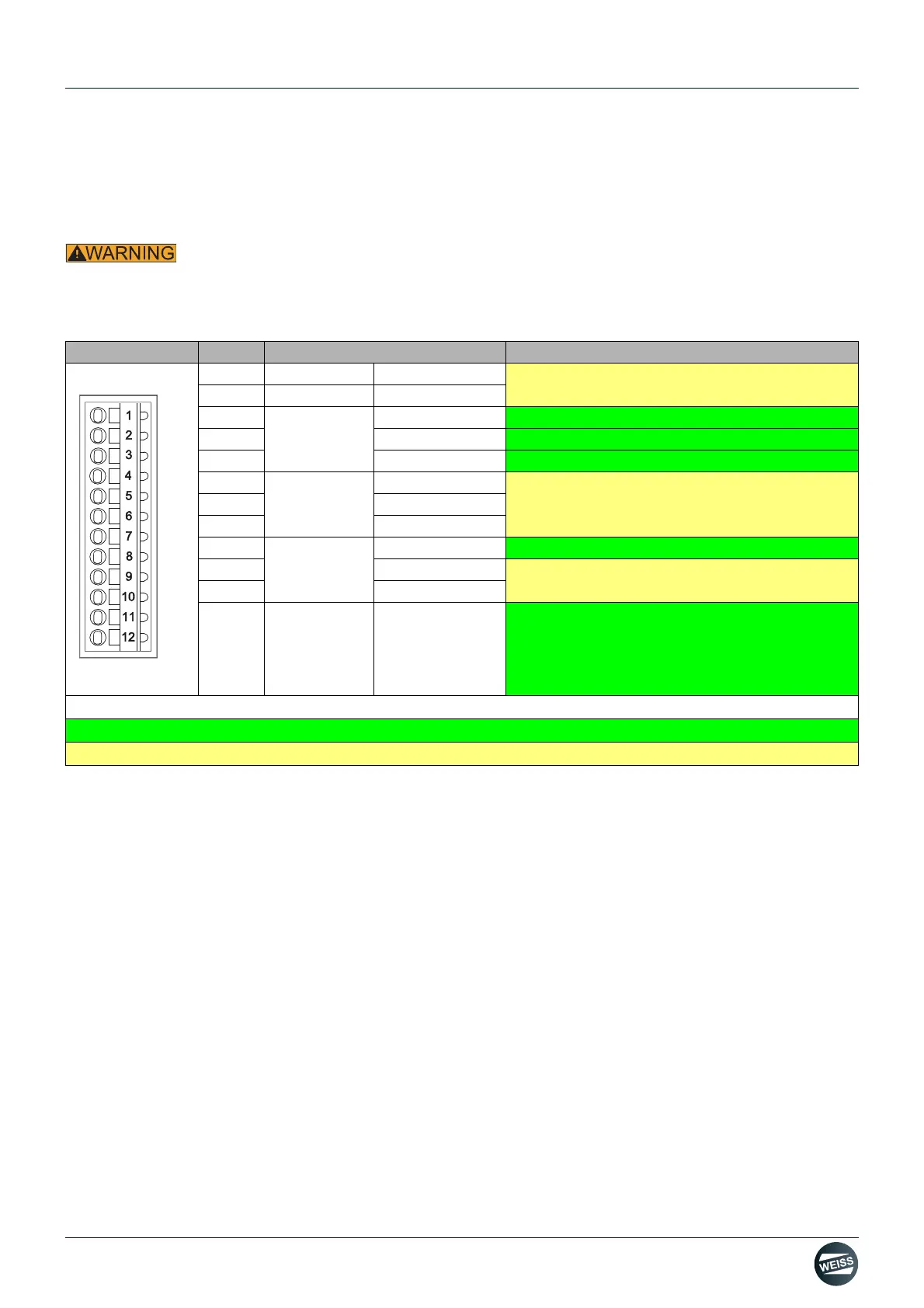
FUNCTION AND SIGNAL DESCRIPTIONS | 4.5 Interface assignment D410-2
4.5 Interface assignment D410-2
4.5.1 Interface X120
Electric shock
Only temperature sensors that meet the safety isolation specifications specified in EN 61800-5-1 may be connected
to terminals "+Temp" and "-Temp". If safe electrical separation cannot be guaranteed (for linear motors or third-party
motors, for example), a Sensor Module External (SME120 or SME125) or Terminal Module TM120 must be used. If
these instructions are not complied with, there is a risk of electric shock!.
1)
Reference potential for DI 17+ / DI 19+ / DI 21+ (or F-DI 0 to F-DI 2; second shutdown path)
2)
Functionality depends on the parameterized Safety Integrated functions.
The functionality of the digital inputs DI 16 to DI 21 depends on the parameterized Integrated Safety functions.
Representation Pin Name Description
1 + Temp
Do not use
2 - Temp
3
F-DI 0
2)
DI 16 STO (+ 24 V)
4 DI 17+
STO (+ 24 V)
5 DI 17-
- M
6
F-DI 1
2)
DI 18 Do not use
7 DI 19+
8 DI 19-
1)
9
F-DI 2
2)
DI 20 Temperature switch for brake resistor
10 DI 21+
Do not use
11 DI 21-
1)
12
M1
Reference potential for:
• DI 16, DI 18 and DI 20 (or F-DI 0 to FDI 2; first
shutdown path)
• DO 16+ (or F-DO 0)
Colour coding in the description:
Green: relevant for EF2
Yellow: Not used for EF2. Do not use!
 Loading...