Manual R06-2016 21 / 172
ROTARY INDEXING TABLE CONTROLLER
EF2...B
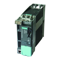
COMPONENT DESCRIPTIONS | 3.1 Power Modules PM240-2
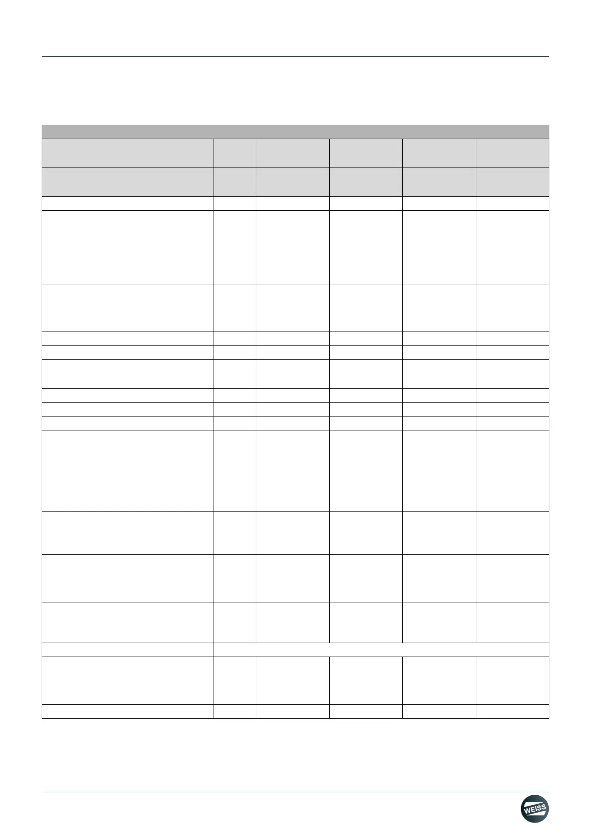
3.1.4 Technical data
Standard Power Modules PM240-2
• Without integrated line filter
6SL3210-
1PB13-0UL0
6SL3210-
1PE16-1UL1
6SL3210-
1PE18-0UL1
6SL3210-
1PE21-1UL0
• With integrated line filter
6SL3210-
1PB13-0AL0
6SL3210-
1PE16-1AL1
6SL3210-
1PE18-0AL1
6SL3210-
1PE21-1AL0
Line supply voltage VAC 1AC200...240 3AC380...480 3AC380...480 3AC380...480
Output current
Rated current I
N
1)
Base-load current IL
1)
Base-load current IH
2)
Peak current Imax
A
A
A
A
1AC50Hz 230 V
3.2
3.2
2.3
4.8
3AC50Hz 400 V
5.9
5.9
4.1
8.9
3AC50Hz 400 V
7,.
7.7
5.9
11.8
3AC50Hz 400 V
10.2
10.2
7.7
15.4
Rated power
• based on IL
• based on IH
kW
kW
0.55
0,37
2.2
1,5
3.0
2,2
4.0
3,0
Rated pulse frequency kHz 4 4 4 4
Efficiency factor η 0,96...0,97 0,96...0,97 0,96...0,97 0,96...0,97
Power loss
3)
at rated current kW 0.04 0.077 0.103 0.128
Cooling air requirement m
3
/s 0.005 0.005 0.005 0.0092
Sound pressure level LpA (1 m) dB < 50 < 50 < 50 < 62
24 V DC supply for the control unit A 1.0 1.0 1.0 1.0
Input current
4)
• Rated current 1AC/3AC
• based on IH 1AC/3AC
• Rated current
• based on IH
A
A
A
A
7.5/4.3
6.6/3.8
--
--
--
--
7.7
6.1
--
--
10.1
8.8
--
--
13.3
11.6
Power mains connection U1/L1, V1/
L2, W1/L3
• Terminal cross-section
mm
2
Clamping
connector
1.5...2,5
Clamping
connector
1.0...2.5
Clamping
connector
1.0...2.5
Clamping
connector
1.5...6.0
Line fuses
• Siemens
• UL, J-type
A
A
10
15
10
30
16
30
20
35
Motor connection U2, V2, W2
• Terminal cross-section
mm
2
Clamping
connector
1.5...2,5
Clamping
connector
1.0...2.5
Clamping
connector
1.0...2.5
Clamping
connector
1.5...6.0
PE connection Included in the clamping connector
Maximum motor cable length
• shielded
• unshielded
m
m
50
100
50
100
50
100
50
100
Degree of protection IP20 IP20 IP20 IP20
 Loading...