Manual R06-201654 / 172
ROTARY INDEXING TABLE CONTROLLER EF2...B
INSTALLATION | 6.1 External braking resistor (option)
6.1.2 Mounting / Connecting the braking resistor
1. Drill boreholes in the control cabinet depending on the dimensions of the brake resistor used (see chapter 6.1.1
„Dimensions, hole patterns“ on page 51).
2. Install the brake resistor in the control cabinet (Please note! The power module is screwed onto the brake resi-
stor. The necessary boreholes have already been made in the brake resistor. The screws are supplied. Ensure
sufficient ventilation).
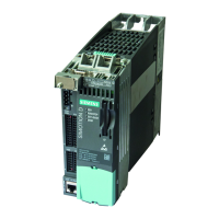
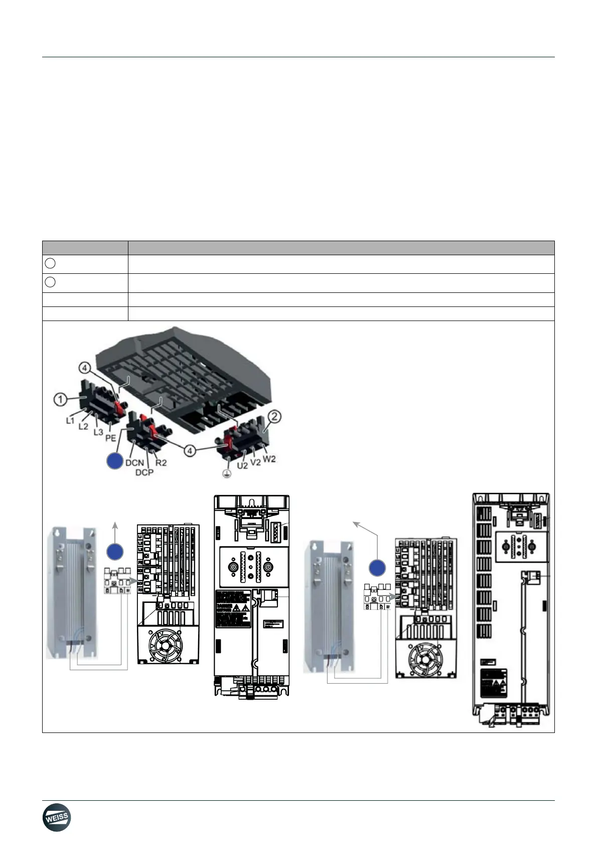
3. Connect the cable of the brake resistor to the terminals DCP and R2 of the power module PM240-2.
The plug connections are located on the bottom side of the power module.
The temperature monitor of the brake resistor can be connected optionally and monitored.
Fig. 25: Braking resistor connection on the PM240-2
Technical data on the drive can be found in chapter chapter 3.2 „External braking resistor (option)“ on page 24
Terminal Name
Plug connection for a brake resistor
Release lever
DCP Braking resistor cable
R2 Braking resistor cable
 Loading...