WPC 2000 User Manual 1128500
Initialization, Setup, and Checkout 3-39
Checking the Emergency-stop Circuit
To check the Emergency-stop circuit, do the following:
1. Run the press in Continuous mode, and press the Emergency Stop button on the Operator
Station. The press should Emergency-stop immediately.
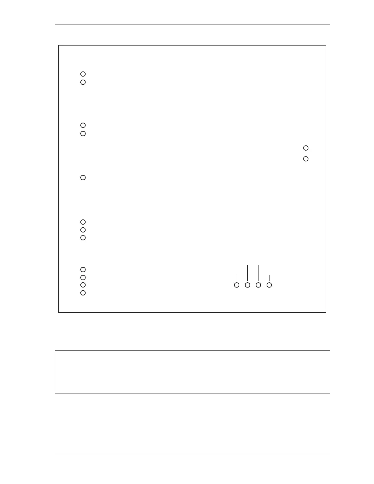
Figure 3-16. WPC 2000 Display Board LED Indicator Map
CHECKING THE EMERGENCY-STOP CIRCUIT IN SINGLE STROKE MODE
If your press does not run in Continuous mode, run this test while the press is making a stroke in
Single-stroke mode.
T
B
7
0
3
151 - Automatic single-stroke select
T
B
7
0
2
149 -
One-hand control select
148 -
Foot control select
147 -
Spare
T
B
7
0
1
143 -
Single stroke select
142 -
Continuous stroke select
145 -
Off stroke select
144 -
Inch stroke select
T
B
7
0
4
154 - Operator station 1 select
153 -
Operator station 2 select
157 -
Micro-inch select
156 -
Set auxiliary cams select
T
B
7
0
5
Display cable transmit
Display cable receive
T
B
7
0
6
J 707
WPC Settings key switch up (+) Spare
Reset/Select button onWPC Settings key switch down (-)
All LEDs are red except the Display cable
receive LED, which is yellow. Pin numbers
associated with LEDs are shown in bold.
LED positions on board are represented
schematically.

 Loading...