WPC 2000 User Manual 1128500
Installation 2-29
The cross-checked input pairs generate a fault either when one or both inputs in the pair are
open or when the inputs “disagree” (i.e., one input is open, the other closed) for longer than
100 mS. Cross-checked input pair 10/11 can be used to detect critical safety problems such as
the removal of die receptacle blocks.
Since faults for input 7 and cross-checked input pair 10/11 open the Lockout relay, you can
wire this relay to your motor starter so that ungrounding of input 7 or of either input in the
input pair will shut off the motor.
To clear the “Loc” message on the LED display, turn the Stroke Select switch to OFF and then
back to INCH (see Wiring the Lockout Relay, next section, and Lockout Message, page 5-3).
To wire the user inputs, run conductors from the appropriate terminal number on the Main
Processor board to your equipment and then back to either +24 Vdc or ground, as shown in
Table 2-3 and Figure 2 at the end of the manual. (There are several available “Ground” and
“+24 Vdc” terminals on the Main Processor board from which to choose.) After you have
wired the inputs you will use, be sure to bypass all the unused inputs by connecting them to
+24 Vdc or Ground.
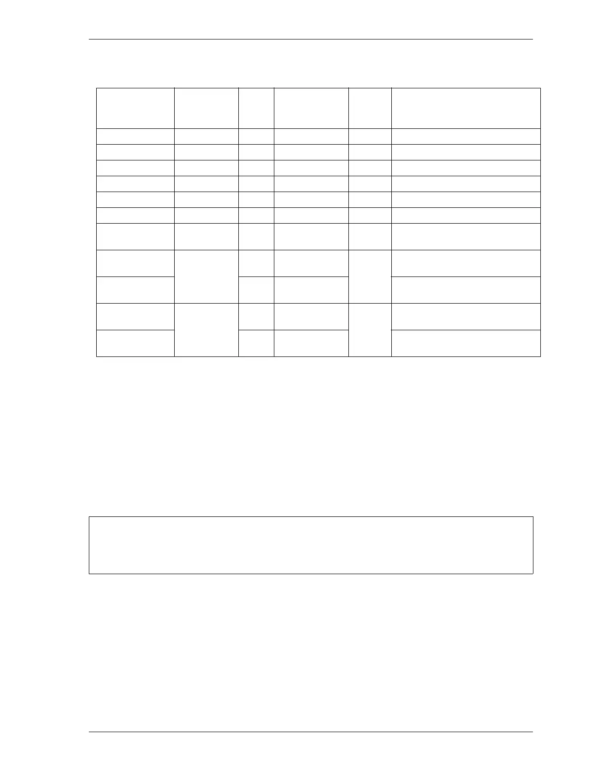
Table 2-3. WPC 2000 User Inputs: Stop Types, Fault Codes, and Wiring Connections
User Input
(Interlock) Stop Type
Pin
#
Jumper
Connection
(Bypass)
Fault
Code
Name of Auxiliary
Equipment
User 1 ESTOP 21 +24 Vdc 51
User 2 ESTOP 82 +24 Vdc 52
User 3 TOP STOP 71 +24 Vdc 53
User 4 ESTOP 83 Ground 54
User 5 TOP STOP 72 Ground 55
User 6 TOP STOP 84 Ground 56
User 7 ESTOP/
LOCKOUT
73 Ground 57
User 8 paired
with 9
ESTOP
85 Ground
58, 17
User 9 paired
with 8
74 Ground
User 10 paired
with 11
ESTOP/
LOCKOUT
86 Ground
50, 18
User 11 paired
with 10
18 Ground
ALL SIGNAL GROUNDS MUST BE CONNECTED THROUGH THE MAIN PROCESSOR BOARD
Connect all signal grounds through pins on the WPC 2000 Main Processor board.

 Loading...