1128500 WPC 2000 User Manual
2-56 Installation
2. Determine a convenient location to mount the display and selector switches in your
enclosure or console. Mount the display so that operators and setup personnel can easily
see the readouts and reach the switches. Make sure that all switches are no more than 1 ft.
(300 mm) from the display.
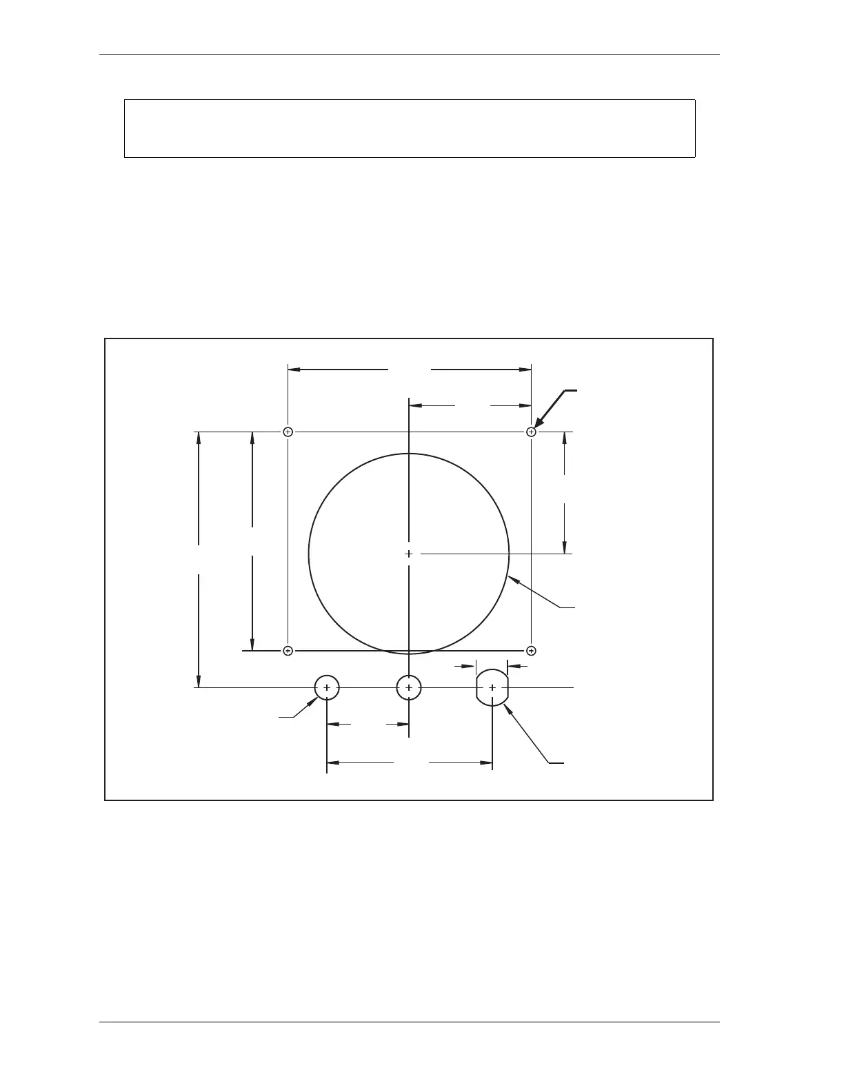
3. Cut or punch holes in your enclosure or console for the display, selector switches, and four
#6-32 x 5/8 studs. Refer to Figure 2-30, below, for cutout dimensions for the display, to
Figure 2-29, page 2-55 for cutout dimensions for the selector switches.
4. Install the four #6-32 x 5/8 studs from inside the enclosure or console.
5. Mount the Display board on the four studs with the standoffs and lock nuts, making sure
that the LED display is at the top facing outward.
6. Orient the label correctly from outside the enclosure or console to match the cutouts, then
remove the protective paper from the label and carefully affix it.
Install selector switches within 1 ft. (300 mm) of the Display board.
Figure 2-30. WPC 2000 Display Board Kit: Mounting and Cutout Dimensions
Dimensions:
inches (mm)
2.500
(63.5)
5.000
(127.0)
0.500 (12.7) DIA.
2 places
0.64 (16.3)
4.12
(104.6)
4.500
(114.3)
5.235
(133.0)
3.400
(86.4)
0.76 (19.3)
1.700
(43.2)
6-32 x 0.625 studs
(on far side)
4 places
2.500
(63.5)
DIA.
DIA.

 Loading...