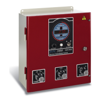
1128500 WPC 2000 User Manual
2-30 Installation
You can add up to 20 more non-control-reliable user inputs and up to 4 more control-reliable,
cross-checked user inputs to your WPC 2000 by purchasing the Option 1 “daughter” board,
which you install on the WPC 2000 Main Processor board. If you are interested in this
product, contact your local Wintriss representative or call Wintriss Tech. Support. To install,
wire, and troubleshoot the Option 1 board, refer to Appendix C.
Wiring the Lockout Relay
The Lockout relay, which is designed to be wired to critical press functions such as the motor
starter, provides an added safety feature to WPC 2000. Whenever a serious error condition
occurs, the “Loc” message will appear in the digital LED display. To clear the “Loc”
message, turn the Stroke Select switch to OFF, then back to INCH or one of the other
operating modes.
Wire the function you want to be controlled by the Lockout relay to TB 301 on the DSV/
Lockout relay board, which is located in the upper left corner (see Figure 2-12, page 2-23) or
lower right corner (see Figure 2-13, page 2-24) of the WPC 2000 Main Processor board.
Wiring connections are shown in Table 2-4 and in Figures 13 (Herion DSV), 14 (Ross Serpar
DSV), and 17 (Ross DM2 DSV) at the end of the manual.
Wiring Auxiliary Outputs
WPC 2000 provides three optional Auxiliary outputs that you can use to automate equipment
connected to your clutch/brake control. A summary of wiring connections and change
conditions for these three outputs is provided in Table 2-5, page 2-31. Details about each
output are given following the table. Additional wiring details are provided in Table 2-17,
page 2-62 and in Figure 2 at the back of the manual.
If you do not bypass the unused inputs, WPC 2000 will not work properly.
Table 2-4. Lockout Relay Wiring Connections (DSV/Lockout Relay Board)
TB301
Pin # Signal
97 Lockout relay input
98 Lockout relay output
99 Lockout relay output
NON-SAFETY OUTPUT USED FOR SAFETY FUNCTIONS
Use Auxiliary outputs 1, 2, and 3 for non-safety functions only, such as convenience in automation.
They cannot protect personnel from a moving hazard.
Failure to comply with these instructions will result in death or serious injury.

 Loading...