1128500 WPC 2000 User Manual
2-38 Installation
6. Run the twelve-conductor cable through flexible, liquid-tight conduit to the terminal
points at the cam output assembly. You can use the knockouts directly below the
connectors if you have the cam output enclosure.
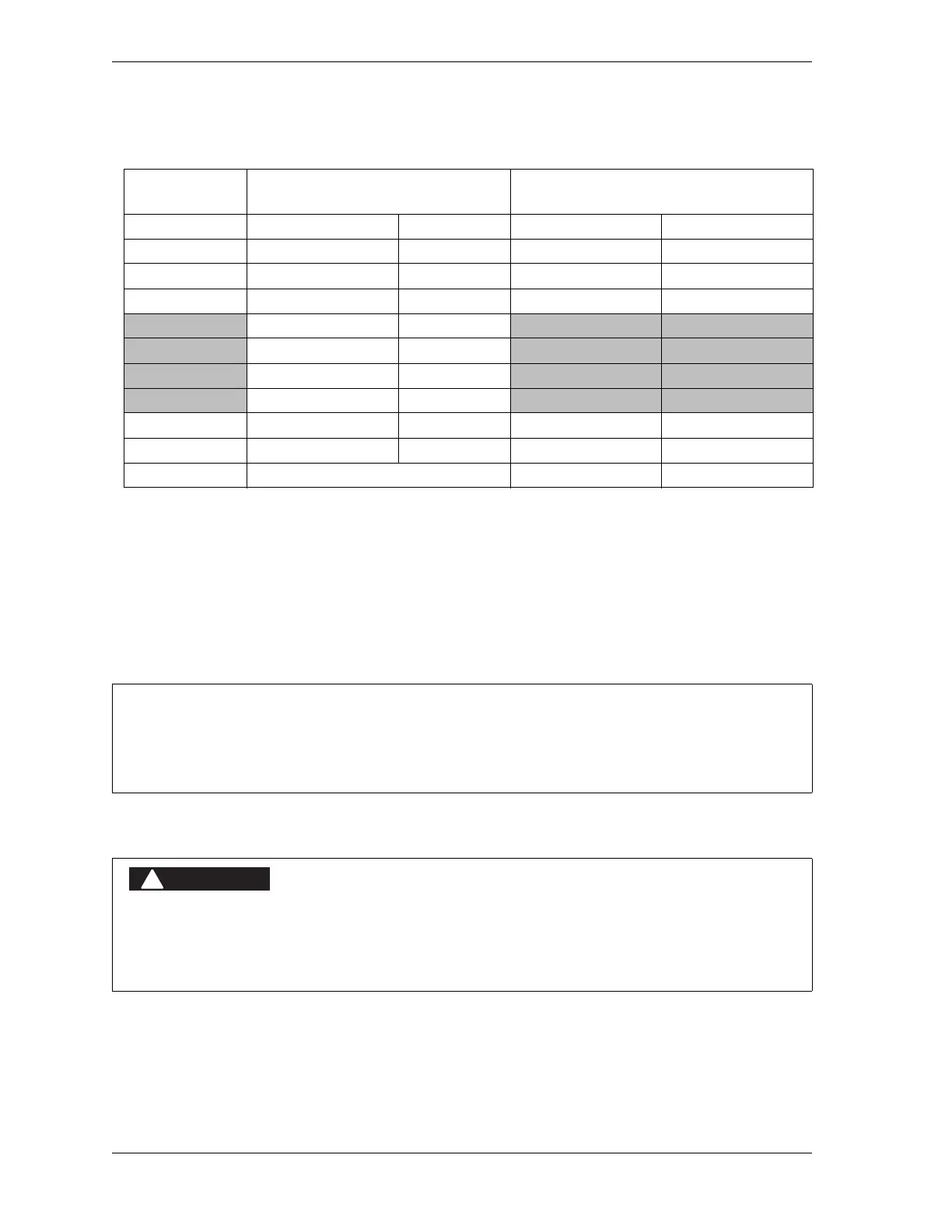
7. Remove the TB1 connector from the Cam Output board, and attach the wires at the other
end of the cable to the terminals shown in Table 2-9 and Figure 6. If you ordered the
enclosure, a wire from the CHAS terminal (pin #1) to a lug on the enclosure should
already be connected. Plug the connector back into its socket when you are finished.
Making Wiring Connections to Cam Relays
To connect the cam relays on the Cam Output board to your equipment, do the following:
Table 2-9. WPC 2000 Main Processor Board (TB109) to Cam Output Assembly (TB1):
Wiring Connections
Wire Color
WPC 2000 Main Proc. Board
Pin # Signal
4-channel Cam I/O Assembly (TB1)
Pin # Signal
Brown 130 Cam 1 7 Channel 1
Violet 129 Cam 2 6 Channel 2
Orange 128 Cam 3 5 Channel 3
Yellow 127 Cam 4 4 Channel 4
126 Counter
125 Zero Cam
124 Spec 1
123 Spec 2
Black 122 Ground 3 Ground
Red 121 +24 Vdc 2 +24 Vdc
Shield Terminate drain wire to ground stud 1 Chassis
TRIM UNUSED WIRES
If your installation does not require all the wires in the cable to be used, trim the unused wires,
cutting them flush with the ends of the cable jacket.
NON-SAFETY OUTPUTS USED FOR SAFETY FUNCTIONS
Use cams for non-safety functions only, such as convenience in automation. They cannot protect
personnel from a moving hazard.
Failure to comply with these instructions will result in death or serious injury.

 Loading...