12.8 H: Terminal Function Selection
668 YASKAWA SIEPC71061753C GA500 Technical Manual
Table 12.64shows the functions that you can set to analog input terminals. Use H3-02 and H3-10 [MFAI Function
Select] to set functions.
Table 12.64 Multi-Function Analog Input Terminal Settings
Setting
Value
Function Reference
0 Frequency Reference 672
1 Frequency Gain 673
2 Auxiliary Frequency Reference 1 673
3 Auxiliary Frequency Reference 2 673
4 Output Voltage Bias 673
5 Accel/Decel Time Gain 674
6 DC Injection Braking Current 674
7 Torque Detection Level 674
8 Stall Prevent Level during Run 674
9 Output Frequency Lower Limit 675
B PID Feedback 675
C PID Setpoint 675
D Frequency Bias 675
Setting
Value
Function Reference
E Motor Temperature (PTC Input) 675
F Through Mode 675
10 Forward Torque Limit 676
11 Reverse Torque Limit 677
12 Regenerative Torque Limit 677
13 Torque Reference / Torque Limit 677
14 Torque Compensation 677
15 General Torque Limit 677
16 PID DifferentialFdbk 677
1F Through Mode 678
30 DWEZ Analog Input 1 678
31 DWEZ Analog Input 2 678
Note:
All analog input scaling uses gain and bias for adjustment. Set the gain and bias values correctly.
Example
Analog Input
Settings
Terminal A1 Setting Frequency Reference
Frequency
Reference When
You Adjust the
Gain Setting
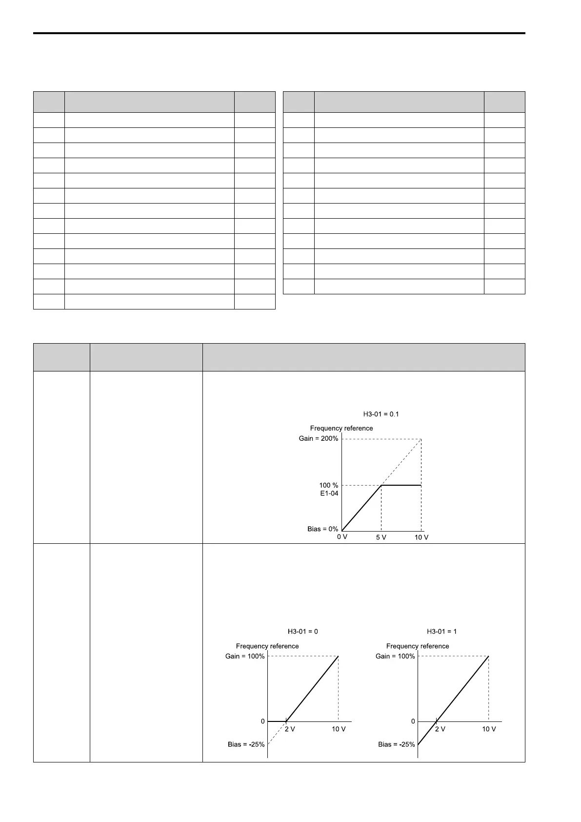
• H3-02 = 0 [Terminal A1 Function
Selection = Frequency Reference]
• H3-03 = 200.0 [Terminal A1 Gain
Setting = 200%]
• H3-04 = 0.0 [Terminal A1 Bias
Setting = 0.0%]
• When you input a 10 V signal, the frequency reference will be 200%.
• When you input a 5 V signal, the frequency reference will be 100%.
When you input a 5 Vor more signal, E1-04 [Maximum Output Frequency] will limit the drive output and the
frequency reference will be 100%.
Frequency
Reference When
You Set the Bias
to a Negative
Number
• H3-02 = 0 [Frequency Reference]
• H3-03 = 100.0 [100.0%]
• H3-04 = -25.0 [-25.0%]
• When you input a 0 V signal, the frequency reference will be -25%.
• When H3-01 = 0 [Terminal A1 Signal Level Select = 0 V to 10 V (Lower Limit at 0)]
– When you input a 0 V to 2 V signal, the frequency reference will be 0%.
– When you input a 2 V to 10 V signal, the frequency reference will be 0% to 100%.
• When H3-01 = 1 [0 V to 10 V (Without Lower Limit)]
– When you input a 0 V to 2 V signal, it enables signals of positive and negative polarities and the motor
rotates in reverse.

 Loading...


