ABB Network Partner AB
Configurable logic
Version 1.0-00
1MRK 580 161-XEN
Page 4 - 26
2.1 Inverter (INV) The configuration logic Inverter (INV) (Fig. 1) has one input, designated
IVnn-INPUT, where nn runs from 01 to 20 for REL 531 and to 79 for
REC 561 and presents the serial number of the block. Each INV circuit
has one output, IVnn-OUT.
Fig. 1 Block diagram of the inverter (INV) function
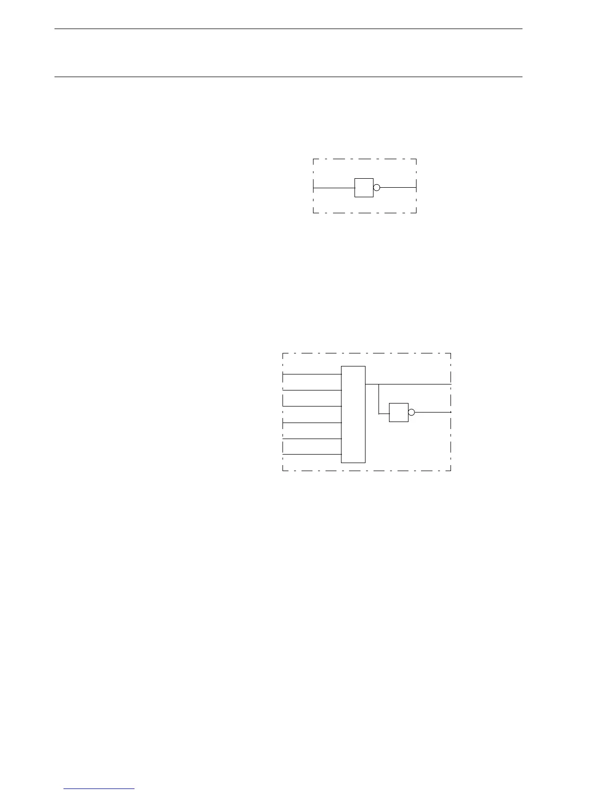
2.2 OR The configuration logic OR gate (Fig. 2) has six inputs, designated Onnn-
INPUTm, where nnn runs from 001 to 040 for REL 531 and to 199 for
REC 561 and presents the serial number of the block, and m presents the
serial number of the inputs in the block. Each OR circuit has two outputs,
Onnn-OUT and Onnn-NOUT (inverted).
Fig. 2 Block diagram of the OR function
INPUT
1
OUT
IVnn
(X80161-1)
≥1
INPUT1
INPUT2
INPUT3
INPUT4
INPUT5
INPUT6
Onnn
1
OUT
NOUT
(X80161-2)
 Loading...


