ABB Network Partner AB
Measurement of alternating
quantities
Version 1.0-00
1MRK 580 159-XEN
Page 7 - 22
• Five input measured currents (I1, I2,..., I5)
• Five input measured voltages (U1, U2,...,U5)
• Mean value of the first, three measured currents (I1, I2, and I3)
• Mean value of the first, three measured voltages (U1, U2, and U3)
• Three-phase, active power P related to the first, three measured cur-
rents and voltages
• Three-phase, reactive power Q related to the first, three measured
currents and voltages
• Mean value of frequencies as measured with voltages U1, U2, and
U3
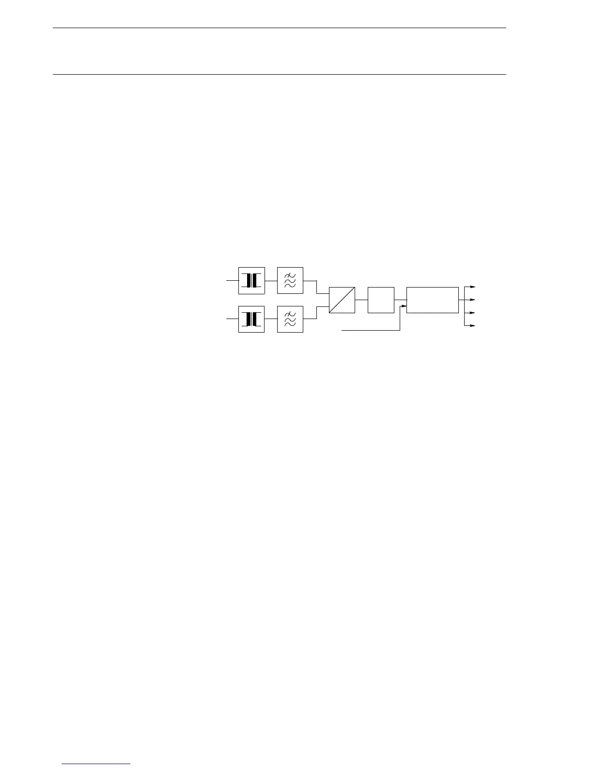
Fig. 4 Simplified block diagram for the function
This information is available to the user for operational purposes. Addi-
tional processing (filtering and calibration) is necessary to obtain the
accuracy sufficient for the purposes of accurate remote measurement.
This additional functionality is optional for the control terminals
(REC 5xx) only.
3Setting
Set the basic terminal parameters under the submenu:
Configuration
AnalogInputs
General
Ur (Ir, fr, CTEarth)
So users can determine the rated parameters for the terminal:
• Rated ac voltage Ur
• Rated ac current Ir (settable only on the terminal)
• Rated frequency fr
• Position of the earthing point of the main CTs (CTEarth), which
determines whether the CT earthing point is towards the protected
object or the busbar.
A
D
5I
5U
PROCESSING
CALIBRATION
SCS
MMI
SMS
LOGIC
DSP
(x80159-4)
 Loading...


