Synchronism and energizing
check for single circuit breaker
with voltage selection
ABB Network Partner AB
1MRK 580 152-XEN
Page 5 - 13
Version 1.0-00
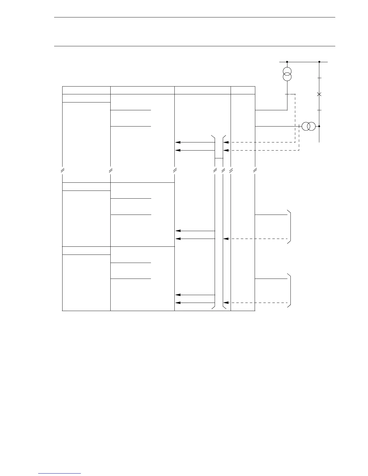
Fig. 4 Voltage connection in a single busbar arrangement. Alterna-
tively, it can be extended up to three bays in one control termi-
nal
1.3.1 Voltage selection for
a single busbar
Single bus is selected on the MMI. Fig. 4 shows the principle for the con-
nection arrangement. One control terminal unit is used for each bay, or it
can alternatively be common for three bays. For the synchronism check
(SYNX) and energizing check function , there is one voltage transformer
at each side of the circuit breaker. The voltage transformer circuit connec-
tions are straightforward, no special voltage selection is needed.
For the synchronism-check and energizing check, the voltage from Bus 1
(SYNX-U-Bus) is connected to the single phase analogue input (U5) on
the control terminal unit.
Bus 1
Bay 1
U-Bus 1
U-Line 1
REC561
SYNCH.CHECK
VOLT SELECTION
I/O BI AI
SYN1
U5
ULX(1)
U-Bus
U-Line
FUSEUB1
FUSEF1
FUSEUB1
FUSEF1
F1
SYN1_UB1OK/FF
SYN1_VTSU
SYN2
U5
UL2
U-Bus
U-Line
FUSEUB1
FUSEF2
SYN2_UB1OK/FF
SYN2_VTSU
SYN3
U5
UL3
U-Bus
U-Line
FUSEUB1
FUSEF3
SYN3_UB1OK/FF
SYN3_VTSU
U-Line 2
FUSEF2
U-Line 3
FUSEF3
U5
ULX(1)
UL2
UL3
From Bay 2
From Bay 3
(X80152-4)
 Loading...


