ABB Network Partner AB
Synchronism and energizing
check for double circuit breakers
and voltage selection
Version 1.0-00
1MRK 580 167-XEN
Page 5 - 34
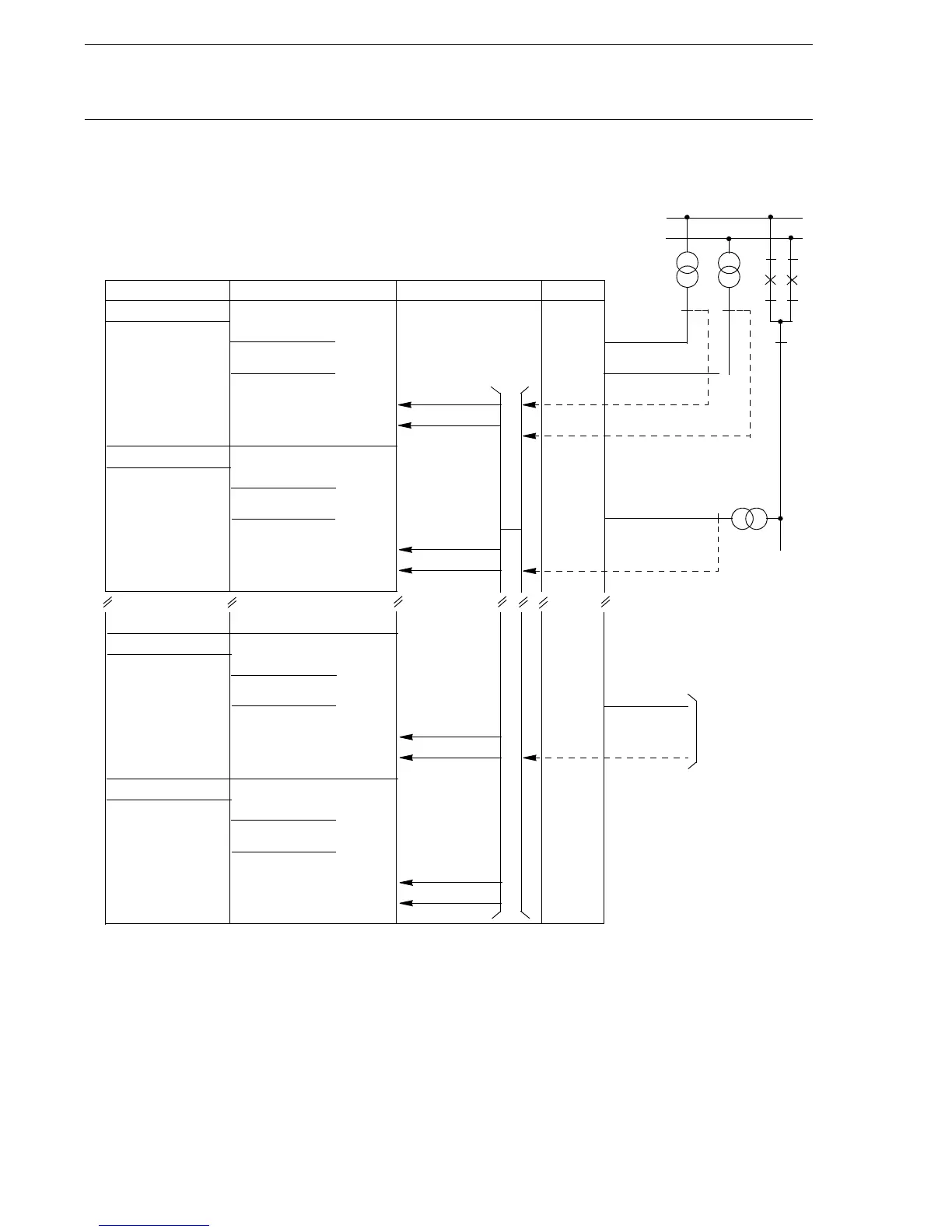
Fig. 4 Voltage connection in a double busbar double breaker
arrangement. Alternatively, it can be extended up to two bays
in one control terminal
1.3 Voltage selection The principle for the connection arrangement is shown in Fig. 4. One con-
trol terminal unit is used for the two circuit breakers in one or two bays
dependent of selected option. There is one voltage transformer at each
side of the circuit breaker, and the voltage transformer circuit connections
are straightforward, without any special voltage selection.
Bus 1
Bay 1
U-Bus 1
U-Line 1
REC561
SYNCH.CHECK
VOLT SELECTION
I/O BI AI
SYN1
U5
ULX(1)
U-Bus
U-Line
FUSEUB1
FUSEF1
FUSEUB1
FUSEF1
F1
SYN1_UB1OK/FF
SYN1_VTSU
SYN3
U5
UL2
U-Bus
U-Line
FUSEUB1
FUSEF2
SYN3_UB1OK/FF
SYN3_VTSU
SYN4
U4
UL2
U-Bus
U-Line
FUSEUB2
FUSEF2
SYN4_UB1OK/FF
SYN4_VTSU
U-Line 2
FUSEF2
U5
ULX(1)
UL2
From Bay 2
(X80167-4)
Bus 2
U-Bus 2
U4
SYN2
U4
ULX(1)
U-Bus
U-Line
FUSEUB2
FUSEF1
SYN2_UB1OK/FF
SYN2_VTSU
FUSEUB2
 Loading...


