ABB Network Partner AB
Breaker-failure protection
Version 1.0-00
1MRK 580 171-XEN
Page 5 - 86
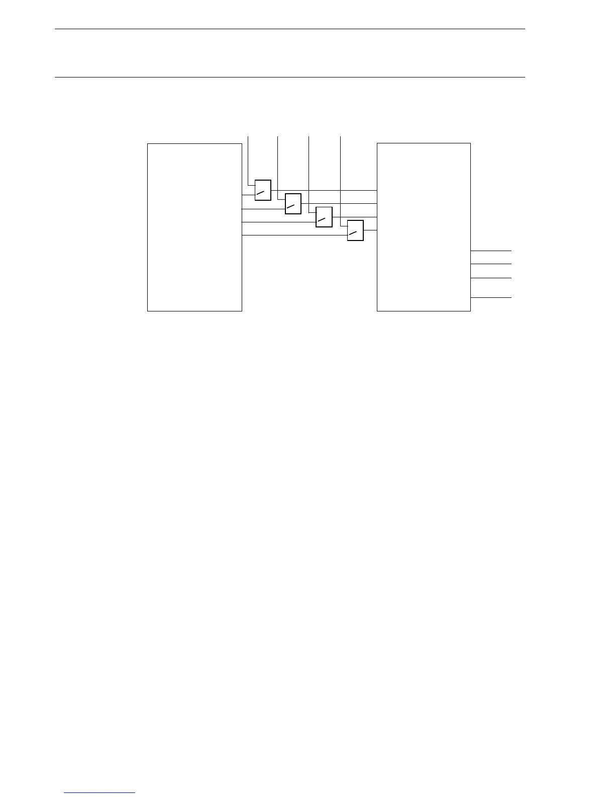
2.1 Input and output
signals
Fig. 4 Input and output signals
The connectable inputs are connectable by configuration to the binary
inputs of the terminal or to other internal functions’ outputs. The outputs
are connectable by configuration to the binary output relays. “Connecta-
bles” and “outputs” can be connected to the free-logic functions of the
unit, OR gates, and in that way add connection links.
2.2 Start functions The breaker-failure protection can be started either internally or exter-
nally. The start pulse is sealed-in as long as the current exceeds the preset
current level, to prevent a restart of the BFP timers in case of a chattering
starting contact.
The preset current level may be set to (0,1 - 2,0)
.
Ir where Ir is 1 or 5 A.
(X80171-4)
1
V
Trip Logic
TRIPL1
TRIPL2
TRIPL3
TPTRIP
STL1
STL2
STL3
ST3PH
RETRIPL1
RETRIPL2
RETRIPL3
BUTRIP
Breaker-failure
protection
1
V
1
V
1
V
External start
Input signals: Start of breaker-failure protection:
BFP--STL1 Phase L1
BFP--STL2 Phase L2
BFP--STL3 Phase L3
BFP--ST3PH Three-phase start
Output signals: Trip:
BFP--BUTRIP Back-up trip
BFP--RETRIPL1 Trip breaker-failure phase L1
BFP--RETRIPL2 Trip breaker-failure phase L2
BFP--RETRIPL3 Trip breaker-failure phase L3
 Loading...


