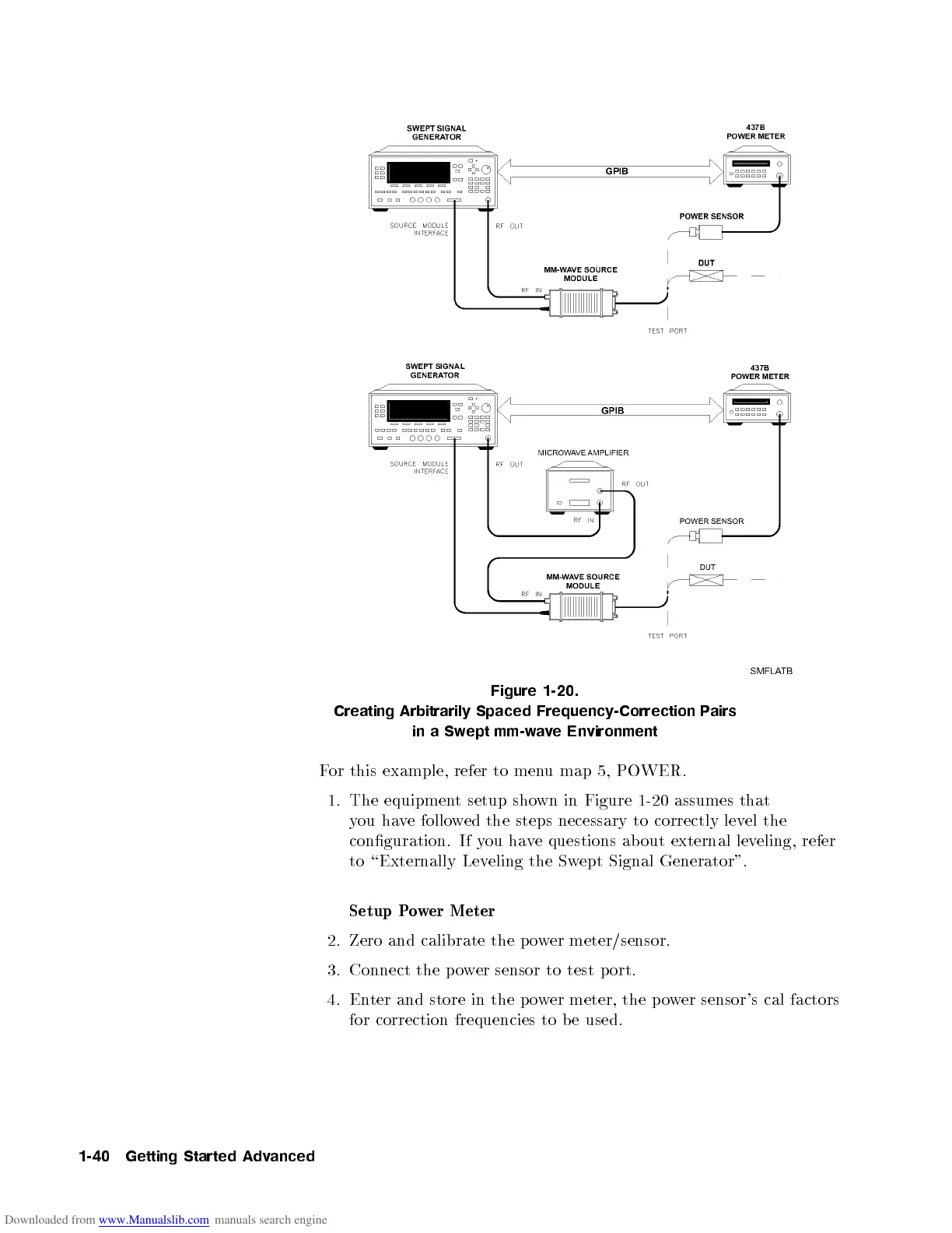
Figure 1-20.
Creating Arbitrarily Spaced Frequency-Correction Pairs
inaSwept mm-wave Environment
For this example, refer to menu map 5, POWER.
1. The equipment setup shown in Figure 1-20 assumes that
you have followed the steps necessary to correctly level the
conguration. If you have questions ab out external leveling, refer
to \Externally Leveling the Swept Signal Generator".
Setup Power Meter
2. Zero and calibrate the p ower meter/sensor.
3. Connect the power sensor to test p ort.
4. Enter and store in the p ower meter, the p ower sensor's cal factors
for correction frequencies to be used.
1-40 Getting Started Advanced

 Loading...


