3 DC Power Supply Operation
Remote Sensing
100 U3606A User’s and Service Guide
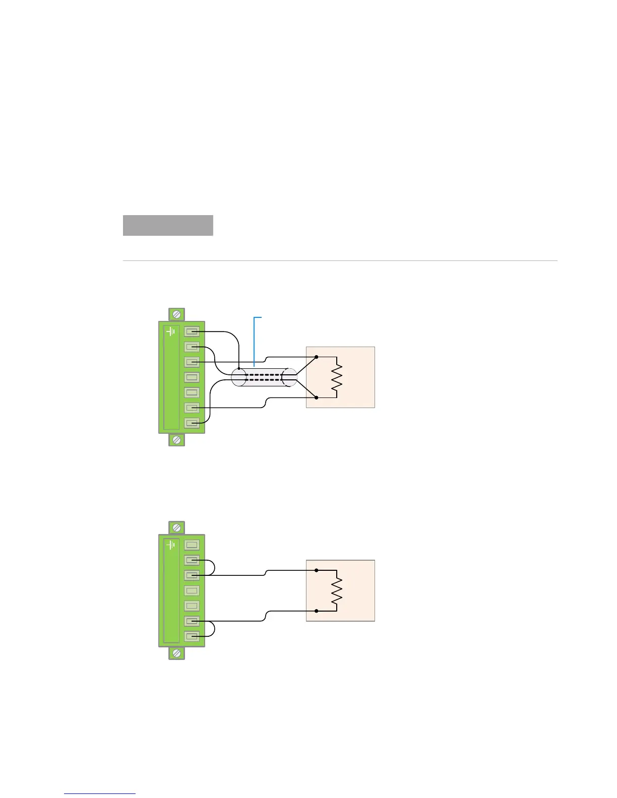
Remote sensing connections
Remote sensing requires connecting the load leads from the rear output
terminals to the load as shown below. Observe the polarity when
connecting the sensing leads to the load.
Figure 3-3 Remote sensing connections
Figure 3-4 Local sensing connections
The metal shorting bars should be removed from the rear output and sense
terminals for remote sensing connections. For local voltage sensing
connections, the sense leads must be connected to the output terminals.
Rear output terminals
Shielded two-wire cable
Rear output terminals
Short bar
Short bar

 Loading...


