Home
Agilent Technologies
Multimeter
U3606A
Agilent Technologies U3606A User Manual
5
of 1
of 1 rating
288 pages
Give review
Manual
Specs
To Next Page
To Next Page
To Previous Page
To Previous Page
Loading...
5
Verification and Performance Tests
Input Connecti
ons
142
U3606A User’s and Service Guide
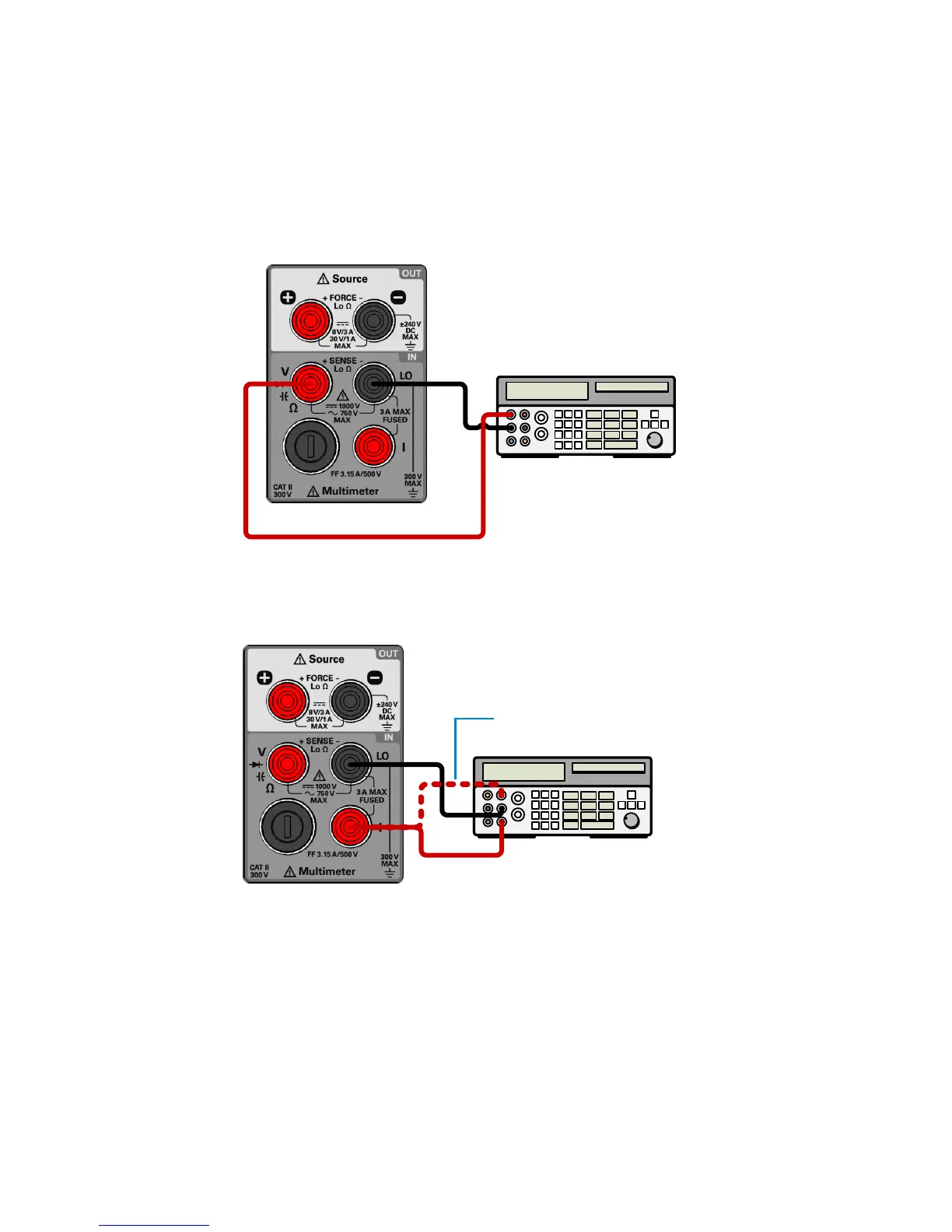
Gain verification test setup
Figure 5-2
T
e
st setup for DC voltage, AC voltage, resistance
, and capacitance gain
verification
Figure 5-3
T
e
st set
up for DC current and
AC curr
ent gain verific
ation
Calibrator
Calibrator
Alternate connecti
on path
163
165
Table of Contents
Default Chapter
2
Restricted Rights Legend
2
Safety Symbols
3
Environmental Conditions
5
In this Guide
8
Table of Contents
13
1 Getting Started
24
Introduction
24
Measurement Features
24
Output Features
25
System Features
25
Initial Inspection
26
Standard Purchase Items
26
Connecting Power to the Instrument
27
Adjusting the Handle
28
Figure 1-1 U3606A Handle Adjustments
28
To Rack Mount the Instrument
29
Stacking the Instrument
30
Figure 1-2 U3606A Stacking Directions
30
Product at a Glance
31
Product Dimensions
31
Figure 1-3 U3606A Dimensions
31
The Front Panel at a Glance
32
Figure 1-4 U3606A Front Panel
32
The Display at a Glance
33
Figure 1-5 VFD Full Display with All Segments Illuminated
33
Table 1-1 U3606A Display Annunciators
33
The Keypad at a Glance
36
Figure 1-6 U3606A Keypad with both Multimeter and Source Operations
36
Table 1-2 U3606A Keypad Functions
37
The Terminals at a Glance
41
Figure 1-7 U3606A Connector Terminals
41
Table 1-3 Input Terminal Connections for Measurement Functions
42
Table 1-4 Output Terminal Connections for Source Functions
43
The Rear Panel at a Glance
44
Figure 1-8 U3606A Rear Panel
44
2 Digital Multimeter Operation
45
Making Measurements
46
Performing Voltage Measurements
47
Figure 2-1 Terminal Connections for Voltage Measurements
47
Table 2-1 DC Voltage Measurement Summary
48
Table 2-2 AC Voltage Measurement Summary
49
Performing Current Measurements
51
Figure 2-2 Terminal Connections for Current Measurements
51
Table 2-3 DC Current Measurement Summary
52
Table 2-4 AC Current Measurement Summary
53
Performing Resistance (2-Wire) Measurements
55
Figure 2-3 Terminal Connections for 2-Wire Resistance Measurements
55
Table 2-5 Resistance Measurement Summary
56
Performing Low-Resistance (4-Wire) Measurements
57
Figure 2-4 Terminal Connections for 4-Wire Resistance Measurements
58
Table 2-6 Low-Resistance Measurement Summary
59
Performing Frequency, Pulse Width, and Duty Cycle Measurements
60
Figure 2-5 Terminal Connections for Frequency, Pulse Width, and Duty Cycle Measurements Via the Voltage Path
60
Figure 2-6 Terminal Connections for Frequency, Pulse Width, and Duty Cycle Measurement Via the Current Path
61
Table 2-7 Frequency Measurement (Voltage Path) Summary
62
Table 2-8 Frequency Measurement (Current Path) Summary
65
Performing Capacitance Measurements
68
Figure 2-7 Terminal Connections for Capacitance Measurements
69
Table 2-9 Capacitance Measurement Summary
70
Performing Continuity Tests
71
Figure 2-8 Terminal Connections for Continuity Tests
71
Table 2-10 Continuity Function Summary
72
Performing Diode Tests
73
Figure 2-9 Terminal Connections for Diode Tests
73
Table 2-11 Diode Function Summary
74
Selecting a Range
76
Setting the Resolution
77
Math Operations
78
Table 2-12 Math Operations Summary
78
Null
79
Dbm Measurements
81
Db Measurements
82
Minmax
84
Limit
86
Hold
89
Triggering the Multimeter
91
Front Panel Triggering
92
Remote Interface Triggering
93
600 DC Power Supply Operation
96
Basic Operation
96
Constant Voltage (CV) Mode
96
Figure 3-1 Constant Voltage Mode Terminal Connections
96
Constant Current (CC) Mode
98
Figure 3-2 Constant Current Mode Terminal Connections
98
Protection Functions
100
Overvoltage Protection (OVP)
100
Overcurrent Protection (OCP)
103
Overvoltage Limit (OV)
106
Overcurrent Limit (OC)
108
Square-Wave Output
110
Table 3-1 Available Frequencies for Square-Wave Output
112
Sweep Functions
115
Ramp Signal
115
Scan Signal
117
Selecting a Range
119
Enabling the Output
120
Remote Sensing
121
Figure 3-3 Remote Sensing Connections
122
Figure 3-4 Local Sensing Connections
122
4 System Related Operation
130
Using the Utility Menu
130
Table 4-1 Utility Menu Key Descriptions
130
Changing Configurable Settings
131
Utility Menu Summary
133
Table 4-2 Utility Menu Item Descriptions
133
Reading Error Messages
136
Reading the Program Code Revision
137
Adjusting the Display Brightness
138
Changing the Power-On State
138
Configuring the Beeper
139
Connecting to a Remote Interface
140
Performing a Self-Test
142
Selecting a Dbm Reference Resistance Value
143
Configuring the Ramp Signal Parameters
144
Table 4-3 Ramp Signal Parameters
144
Configuring the Scan Signal Parameters
146
Table 4-4 Scan Signal Parameters
146
Enable Refresh Hold
148
Enable Data Hold
149
Storing and Recalling Instrument States
150
Storing a State
150
Recalling a Stored State
151
Remote Operation
152
Configuring and Connecting the GPIB Interface
153
Configuring and Connecting the USB Interface
154
SCPI Commands
155
5 Verification and Performance Tests
158
Recommended Test Equipment
158
Table 5-1 Recommended Test Equipment for Performance Verification
158
Connecting the Current Monitoring Resistor
161
General Measurement Techniques
161
Using an Electronic Load
161
Test Considerations
162
Input Connections
163
Zero Offset Verification Test Setup
163
Figure 5-1 Test Setup for Zero Offset (Short) Verification
163
Gain Verification Test Setup
164
Figure 5-2 Test Setup for DC Voltage, AC Voltage, Resistance, and Capacitance Gain Verification
164
Figure 5-3 Test Setup for DC Current and AC Current Gain Verification
164
Output Verification Test Setup
165
Figure 5-4 Test Setup for Frequency Gain Verification
165
Figure 5-5 Test Setup for CV Programming and Readback Accuracy
165
Figure 5-6 Test Setup for CV Load and Line Regulation Verification
166
Figure 5-7 Test Setup for CV Noise Effect Verification
166
Figure 5-8 Test Setup for Load Transient Response Time Verification
167
Figure 5-9 Test Setup for CC Programming and Readback Accuracy
167
Figure 5-10 Test Setup for CC Line and Load Regulation Verification
168
Figure 5-12 Test Setup for Square-Wave Output Verification
169
Verification and Performance Tests Overview
170
Self-Test
171
Performance Verification Tests
172
Zero Offset Verification Test
172
Table 5-2 Zero Offset Verification Test
173
Gain Verification Test
174
Table 5-3 DC Voltage Gain Verification Test
174
Table 5-4 DC Current Gain Verification Test
175
Table 5-5 AC Voltage Gain Verification Test
176
Table 5-6 AC Current Gain Verification Test
177
Table 5-7 Resistance Gain Verification Test
177
Table 5-8 Frequency Gain Verification Test
178
Output Verification Test
179
Table 5-9 Constant Voltage Programming and Readback Accuracy Verification
179
Table 5-10 Constant Voltage Load Effect Verification Test
180
Table 5-11 Constant Voltage Source Effect Verification Test
181
Figure 5-13 Load Transient Response Time
184
Table 5-12 Constant Current Programming and Readback Accuracy Verification
185
Test
185
Table 5-13 Constant Current Load Effect Verification Test
186
Table 5-14 Constant Current Source Effect Verification Test
187
Additional Verification Tests
189
Optional Capacitance Gain Verification Test
189
Table 5-15 Optional Capacitance Gain Verification Test
189
Optional Square-Wave Output Verification Test
190
Table 5-16 Square-Wave Amplitude Output Verification Test
191
Table 5-17 Square-Wave Frequency Output Verification Test
191
Table 5-18 Square-Wave Duty Cycle Output Verification Test
192
6 Calibration Procedures
193
Calibration Overview
194
Closed-Case Electronic Calibration
194
Agilent Technologies Calibration Services
194
Calibration Interval
195
Adjustment Is Recommended
195
Time Required for Calibration
195
Recommended Test Equipment
196
Table 6-1 Recommended Test Equipment for Adjustment Procedures
196
Calibration Process
197
Calibration Security
198
Unsecuring the Instrument for Calibration
198
Changing the Calibration Security Code
201
Resetting the Security Code to the Factory Default
201
Figure 6-1 SECUR Pads Location
202
Calibration Count
204
Calibration Message
205
Using the Front Panel for Adjustments
206
Selecting the Adjustment Mode
206
Entering Adjustment Values
206
Aborting a Calibration in Progress
207
General Calibration Procedure
208
Adjustments Procedures
211
Zero Offset Adjustment
211
Gain Adjustments
213
Table 6-2 Valid Gain Adjustment Input Values
214
Table 6-3 DC Voltage Gain Adjustment
216
Table 6-4 AC Voltage Gain Adjustment
218
Table 6-5 Frequency Gain Adjustment
219
Table 6-6 Resistance Gain Adjustment
220
Table 6-7 DC Current Gain Adjustment
222
Table 6-8 AC Current Gain Adjustment
223
Table 6-9 Capacitance Gain Adjustment
224
Output Adjustments
226
Table 6-10 Valid Output Adjustment Levels
226
Table 6-11 Constant Current Output Adjustment
228
Table 6-12 Constant Voltage Output Adjustment
231
Finishing the Adjustments
235
7 Disassembly and Repair
238
Operating Checklist
238
Cleaning
239
Fuse Replacementto Replace the Power Line Fuse
239
To Replace the Current Input Fuse
242
Electrostatic Discharge (ESD) Precautions
244
Mechanical Disassembly
245
General Disassembly
245
Replaceable Parts
253
Table 7-1 List of Replaceable Parts
253
To Order Replaceable Parts
254
Types of Services Available
255
Repackaging for Shipment
256
8 Characteristics and Specifications
257
Product Characteristics
258
Digital Multimeter Specifications
260
Specification Assumptions
260
DC Specifications
261
Table 8-1 DC Accuracy Specifications ± (% of Reading + % of Range)
261
Table 8-2 AC Accuracy Specifications ± (% of Reading + % of Range)
263
AC Specifications
263
Frequency Specifications
264
Table 8-3 Frequency Accuracy Specifications ± (% of Reading + % of Range)
264
Table 8-4 Frequency Sensitivity for Voltage Measurement
264
Duty Cycle and Pulse Width Specifications
265
Table 8-6 Duty Cycle and Pulse Width Resolution and Accuracy
265
Table 8-5 Frequency Sensitivity for Current Measurement
265
Operating Specifications
266
Table 8-7 Reading Speed (Typical)
266
Supplementary Specifications
267
DC Power Supply Specifications
271
Safety Considerations
271
Specifications Assumptions
271
Performance Specifications
272
Table 8-8 DC Power Supply Performance Specifications
272
Supplementary Specifications
274
Table 8-9 Square-Wave Output Specifications
275
Table 8-10 Scan Output Specifications
277
Table 8-11 Ramp Output Specifications
277
9 List of Error Messages
280
Error Messages
280
Command Errors
281
Table 9-1 List of Command Errors
281
Execution Errors
282
Table 9-2 List of Execution Errors
282
Internal Errors
283
Query Errors
283
Device Specific Errors
283
Table 9-3 List of Internal Errors
283
Table 9-4 List of Query Errors
283
Table 9-5 List of Device Specific Errors
283
Self-Test Errors
284
Table 9-6 List of Self-Test Errors
284
Calibration Errors
285
Table 9-7 List of Calibration Errors
285
5
Based on 1 rating
Ask a question
Give review
Questions and Answers:
Need help?
Do you have a question about the Agilent Technologies U3606A and is the answer not in the manual?
Ask a question
Agilent Technologies U3606A Specifications
General
Brand
Agilent Technologies
Model
U3606A
Category
Multimeter
Language
English
Related product manuals
Agilent Technologies U3402A
127 pages
Agilent Technologies U1252B
191 pages
Agilent Technologies U1241B
89 pages
Agilent Technologies U1253B
225 pages
Agilent Technologies U1242B
89 pages
Agilent Technologies U1242A
85 pages
Agilent Technologies U1241A
85 pages
Agilent Technologies U1231A
133 pages
Agilent Technologies U1251A
169 pages
Agilent Technologies 34420A
294 pages
Agilent Technologies 34401A
242 pages
Agilent Technologies 34410A
144 pages

 Loading...


