6 Calibration Procedures
Adjustments procedures
212 U3606A User’s and Service Guide
2 Press Shift > EXT to enable remote sensing. When the U3606A is
operating in remote sensing mode, the EXT annunciator on the front
panel is illuminated.
3 Perform step 2 through step 7 of the “CV output adjustment procedure
— front output terminals” on page 207. Refer to Table 6- 12 on page 209
for the constant voltage output adjustment items.
4 Repeat step 3 through step 7 of the “CV output adjustment procedure —
front output terminals” on page 207 for the S1 (30 V/1 A) range. Press
Voltage to select the S1 range (the S1 annunciator is illuminated).
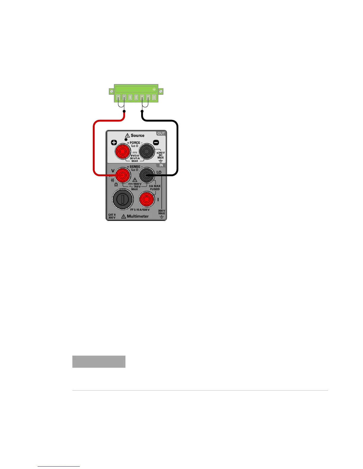
For adjustment item “LOAd”, connect an additional 30 Ω, 50 W load
across the rear panel + and – output terminals. Leave the connections
from the output terminals (+ and –) to the input terminals (V and LO)
intact.
Do not remove the short bar between the rear panel sense terminals (+S
and –S) are the rear panel output (+ and –) terminals. See “Remote
sensing connections” on page 100 for more information on how to
connect the load leads.

 Loading...


