screw. This screw must be replaced at
each reassembly.
•
Tighten the second camshaft gear fix-
ing screw to exactly the torque speci-
fied.
•
Remove the crankshaft locking tool.
•
Turn the crankshaft back to the previous position in which the camshaft and U bolt holes
were aligned; insert the reference pin while checking with the crankshaft reference pin, that
the flywheel side hole and the hole on the crankshaft are perfectly aligned.
•
If this is not the case, repeat the timing operations.
Specific tooling
020851Y Camshaft timing pin
020852Y Crankshaft timing pin
Front head removal
•
Remove both head covers, the alter-
nator side cover and remove the cap
on the clutch cover in order to rotate
the crankshaft.
•
Remove the O ring.
•
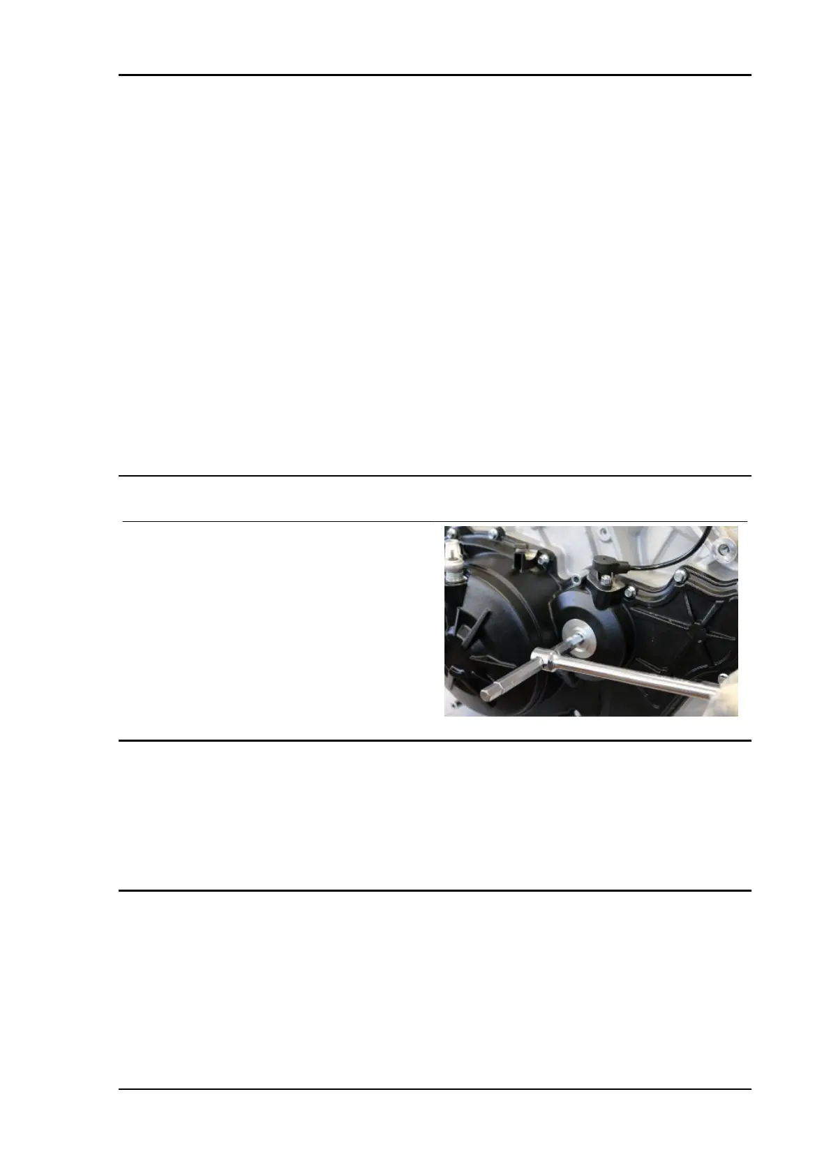
Turn the crankshaft from the hole on the clutch cover.
•
Move cylinder piston 1 (left rear piston) to the overlap TDC;
•
Turn the crankshaft 150° in the engine rotation direction (direction of travel), in order to align
the hole on the intake camshaft with the specific hole on the U bolt; this ensures that all the
front cylinder bank valve springs are decompressed.
RSV4 RR-RF Engine
ENG - 315

 Loading...