4. Physical installation
4.2 Connecting the projector with the power n et
WARNING: The total electrical installation should be p rotected by an appropriate rated an d readily accessi-
ble disconnect sw itch, circuit breakers and ground fault current interrupters. The installation shall be done
according to the local electrical installation codes.
CAUTION: ALL P OWE R CONNEC TIONS to the DP2K SL P-series are made to the 3- slot terminal block located
in a sealed co mp artment behind the rear cover of the projector.
CAUTION: The cross-sectional area of the conductors in the Power Supply Cord shall be not less than 2.5
mm
2
(12 AWG).
Necessary tools
• Medium size flat screw driver (4 mm x 100 mm )
• Torque flat screw driver (medium size)
• Large size flat screw driver (8 mm x 150 mm )
• Open end wrench 24 mm
Necessary parts
Certified AC power supply cord 2.5 mm
2
(12 AWG), min. 300 V. Take into account that the c able gland of the projector allows a
cable diam eter from 8 to 13 mm.
How to connect the main AC power with the DP2K SLP-series projector?
1. Remove the rear cover of the pr ojector. See procedure "Removal of the rear cover", pa ge 133.
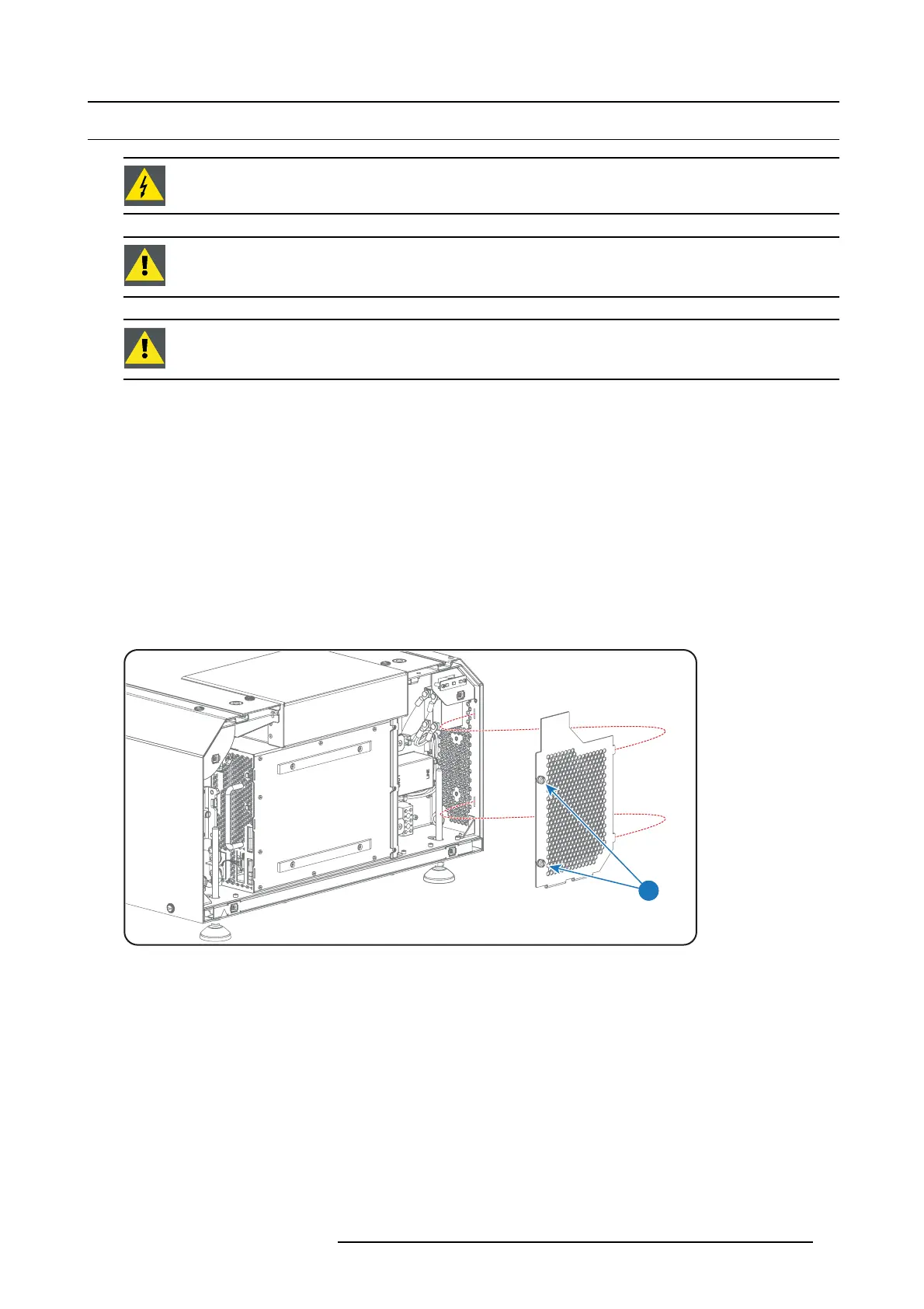
2. Remove the cover of the m ain AC compartment by releasing the two captive thumb screws (reference 1 ) .
1
Image 4-5
3. Guide the AC power supply cord (reference 2 image 4-6) through the cable gland (reference 3 im age 4-6) and connect the wires
to the 3 -terminal strip (reference 6 ima
ge 4-6) as illustrated. Use a torque screw driver to fasten the screws of the 3-terminal strip
with a torque of 1.7Nm (1. 2 5 lb f*f t).
Warning: Connect first the P E wire (reference 4 image 4-6), then the other wires (reference 5 image 4-6).
Tip: Check for good fixation by pulling on each wire.
R5906847 DP2K SLP SERIES 02/06/2017
31
 Loading...


