MY23P0a -52_1.0_11.10.2022
190
Operation
6.19 Using the on-board computer
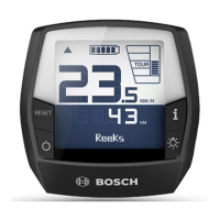
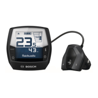
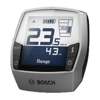
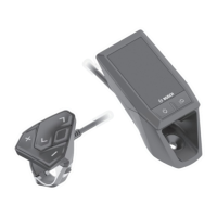
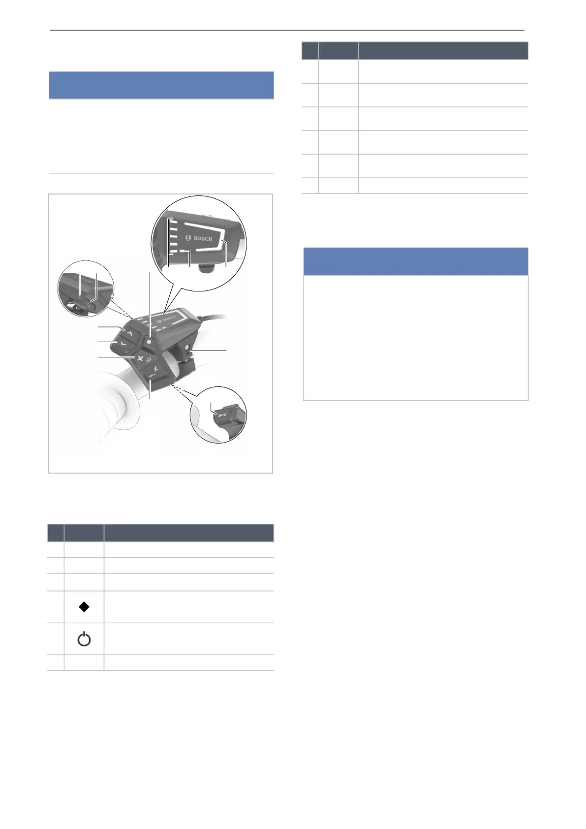
Figure 175: Overview of BOSCH LED Remote on-board
computer
6.19.1 Using the diagnosis port
The diagnosis connection is only designed for
maintenance purposes and is not suitable for
connecting external devices.
Keep the diagnosis port flap closed at all times
to ensure no dust or moisture can penetrate
through the port.
6.19.2 Charging the on-board computer
battery
If both the charge level in the battery and the on-
board computer’s internal battery are low, the on-
board computer battery can be charged via the
diagnosis port.
Connect the internal battery to a power bank or
another suitable power source with a
USB type C® cable. (charge voltage: 5 V;
charging current: max. 600 mA).
Notice
Never use on-board computer, the display or
the display mount as a handle. If the on-board
computer, display or display mount are used to
lift the pedelec, components can become
irreparably damaged.
Symbol Designation
1 Selected level of assistance indicator
2 ABS indicator (optional)
3 Battery level indicator (on-board computer)
4 Select button
5 On-Off button (on-board computer)
6 Ambient light sensor
Table 71: Overview for on-board computer
7
>
Increase brightness button/
forward button
8 < Decrease brightness button/
back button
9 + Plus button/
light button
10 – Minus button/
push assist button
11 Diagnosis connection (for maintenance pur-
poses only)
12 Mount
Notice
A USB connection is not a waterproof plug
connection. Any moisture penetrating through the
USB port may trigger a short circuit in the on-
board computer.
Never connect an external device.
Regularly check the position of the rubber
cover on the USB port and adjust it as
necessary.
Symbol Designation
Table 71: Overview for on-board computer
 Loading...