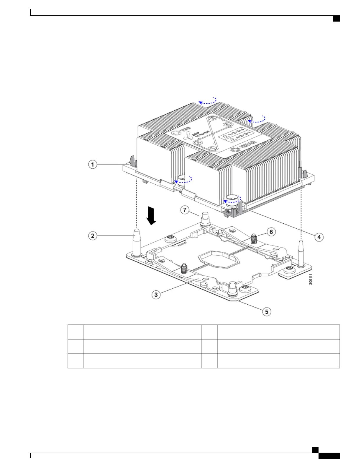
Note the alignment features. The pin 1 angled corner on the heatsink must align with the pin 1 angled corner on the
CPU socket. The CPU-socket posts must align with the guide-holes in the assembly.
Figure 33: Installing the Heatsink/CPU Assembly to the CPU Socket
Angled corner on heatsink (pin 1 alignment feature)4Guide hole in assembly (two)1
Angled corner on socket (pin 1 alignment feature)5CPU socket alignment post (two)2
-CPU socket leaf spring3
c) Set the heatsink with CPU assembly down onto the CPU socket.
d) Use the T-30 Torx driver that is supplied with the replacement CPU to tighten the four captive nuts that secure the
heatsink to the motherboard standoffs.
Cisco UCS C240 M5 Server Installation and Service Guide
79
Maintaining the Server
Replacing CPUs and Heatsinks
 Loading...