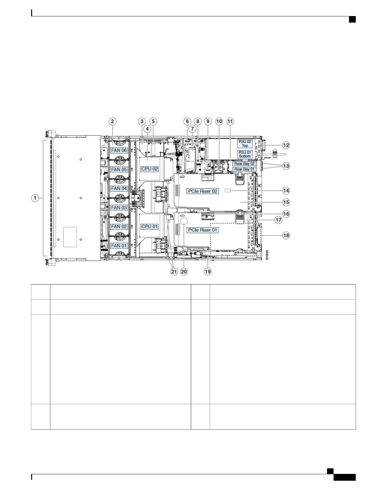
Serviceable Component Locations
This topic shows the locations of the field-replaceable components and service-related items. The view in the
following figure shows the server with the top cover removed.
Figure 5: Cisco UCS C240 M5 Server, Serviceable Component Locations
Rear-drive backplane assembly11Front-loading drive bays.1
Power supplies (hot-swappable when redundant as 1+1)12Cooling fan modules (six, hot-swappable)2
Rear 2.5-inch drive bays:
•
•
All other C240 M5 PIDs support up to two drives:
◦
When using a hardware-RAID controller card
in the server, SAS/SATA drives or NVMe
SSDs are supported in the rear bays.
◦
When using software RAID in the server, only
NVMe SSDs are supported in the rear bays.
13DIMM sockets on motherboard (up to 12 per CPU)
Not visible under air baffle in this view.
See DIMM Population Rules and Memory Performance
Guidelines , on page 70 for DIMM slot numbering.
3
Trusted platform module (TPM) socket on motherboard
(not visible in this view)
14CPUs and heatsinks (up to two)
Not visible under air baffle in this view.
4
Cisco UCS C240 M5 Server Installation and Service Guide
7
Overview
Serviceable Component Locations
 Loading...