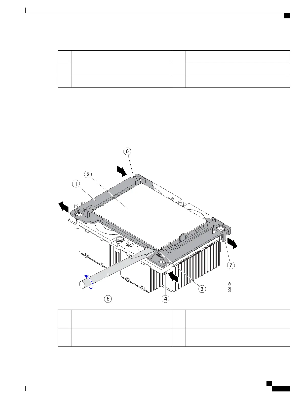
CPU socket on motherboard4Heatsink1
T-30 Torx driver5Heatsink captive nuts (two on each side)2
-CPU carrier (below heatsink in this view)3
Step 2
Separate the heatsink from the CPU assembly (the CPU assembly includes the CPU and the plastic CPU carrier):
a) Place the heatsink with CPU assembly so that it is oriented upside-down.
Note the thermal-interface material (TIM) breaker location. TIM BREAKER is stamped on the CPU carrier next to
a small slot.
Figure 30: Separating the CPU Assembly From the Heatsink
CPU-carrier inner-latch nearest to the TIM breaker
slot
4CPU carrier1
#1 flat-head screwdriver inserted into TIM breaker
slot
5CPU2
Cisco UCS C240 M5 Server Installation and Service Guide
75
Maintaining the Server
Replacing CPUs and Heatsinks
 Loading...