Installation of the equipment must comply with local and national electrical codes.
Statement 1074
Warning
Do not mix power supply types or wattages in the server. Both power supplies must be identical.Note
As instructed in the first step of this wiring procedure, turn off the DC power source from your facility’s
circuit breaker to avoid electric shock hazard.
Caution
Step 1
Turn off the DC power source from your facility’s circuit breaker to avoid electric shock hazard.
The required DC input cable is Cisco part CAB-48DC-40A-8AWG. This 3-meter cable has a 3-pin connector
on one end that is keyed to the DC input socket on the power supply. The other end of the cable has no connector
so that you can wire it to your facility’s DC power.
Note
Step 2
Wire the non-terminated end of the cable to your facility’s DC power input source.
Step 3
Connect the terminated end of the cable to the socket on the power supply. The connector is keyed so that the wires align
for correct polarity and ground.
Step 4
Return DC power from your facility’s circuit breaker.
Step 5
Press the Power button to boot the server to main power mode.
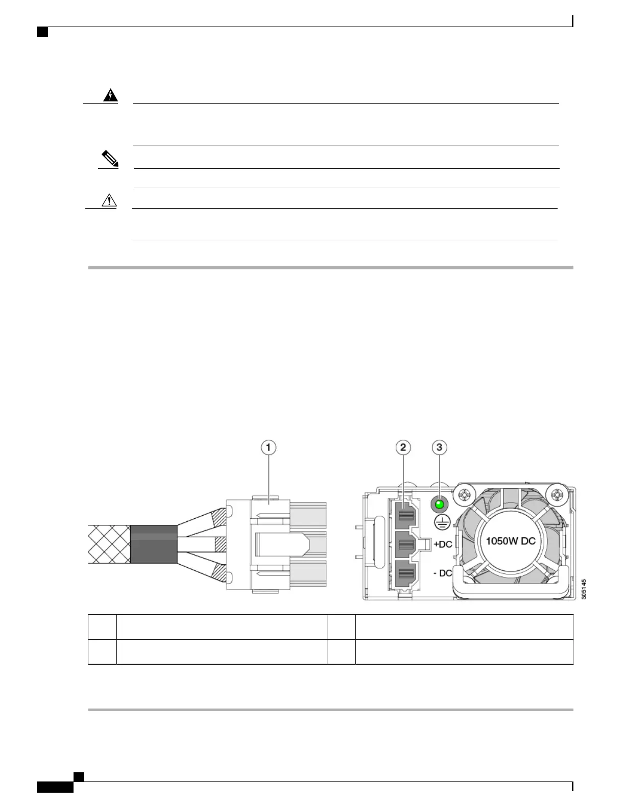
Figure 40: Replacing DC Power Supplies
PSU status LED3Keyed cable connector (CAB-48DC-40A-8AWG)1
-Keyed DC input socket2
Step 6
See Grounding for DC Power Supplies, on page 93 for information about additional chassis grounding.
Cisco UCS C240 M5 Server Installation and Service Guide
92
Maintaining the Server
Replacing Power Supplies
 Loading...