Product Manual – DOC. 8432A Crestron Pyng OS 2 for CP4-R • 41
a. Select the appropriate input port from the provided options.
b. If applicable, select the sensor monitoring state (On or Off).
c. If applicable, select the sensor contact states when turning off the sensor
device (
Contacts Are Open or Contacts Are Closed).
d. Tap the checkbox next to Enable Pull-Up Resistor to enable or disable using a
pull-up resistor for the hardware connection. A checked box indicates an
enabled pull-up resistor.
6. Tap the Test tab to view and test the configured device function(s). The
hardware connection for the device function(s) must be configured before they
may be tested.
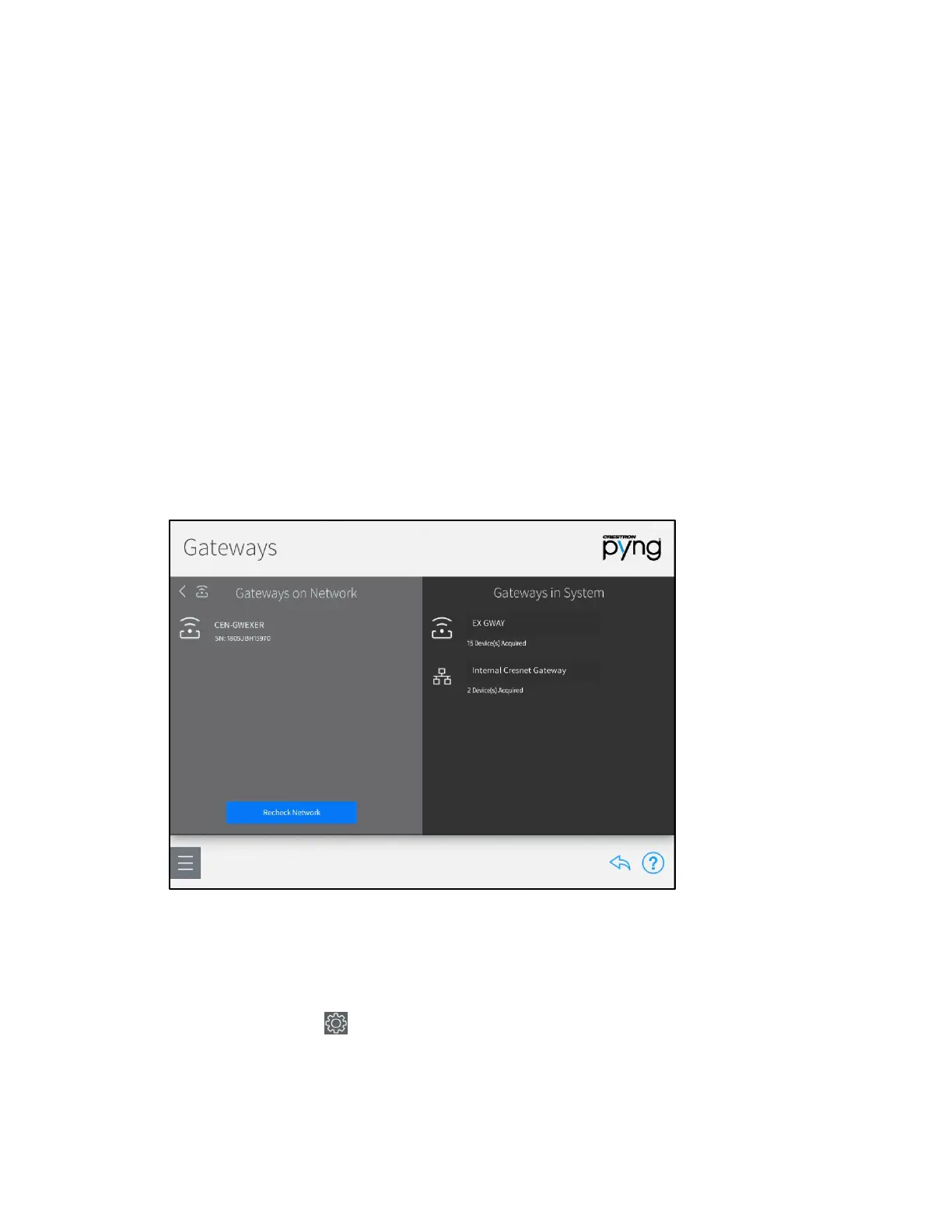
Manage Gateways
Tap Manage Gateways in the Device Types menu to scan the local network for any
gateways that may be added to the Crestron Pyng system. Discovered gateways appear
under the
Gateways on Network menu.
Gateways Screen
Tap the plus button (+) next to a discovered gateway to add it to the system. A system
may contain up to 15 gateways with a maximum of 50 paired devices per gateway.
Once a gateway has been added to the system, select it from the Gateways in System
menu to access the following options.
Tap the gear button next to the gateway name to display a Settings dialog box,
which is used to configure gateway settings.
 Loading...