AX-Series Motion Controller Instructions Manual Chapter 2
148
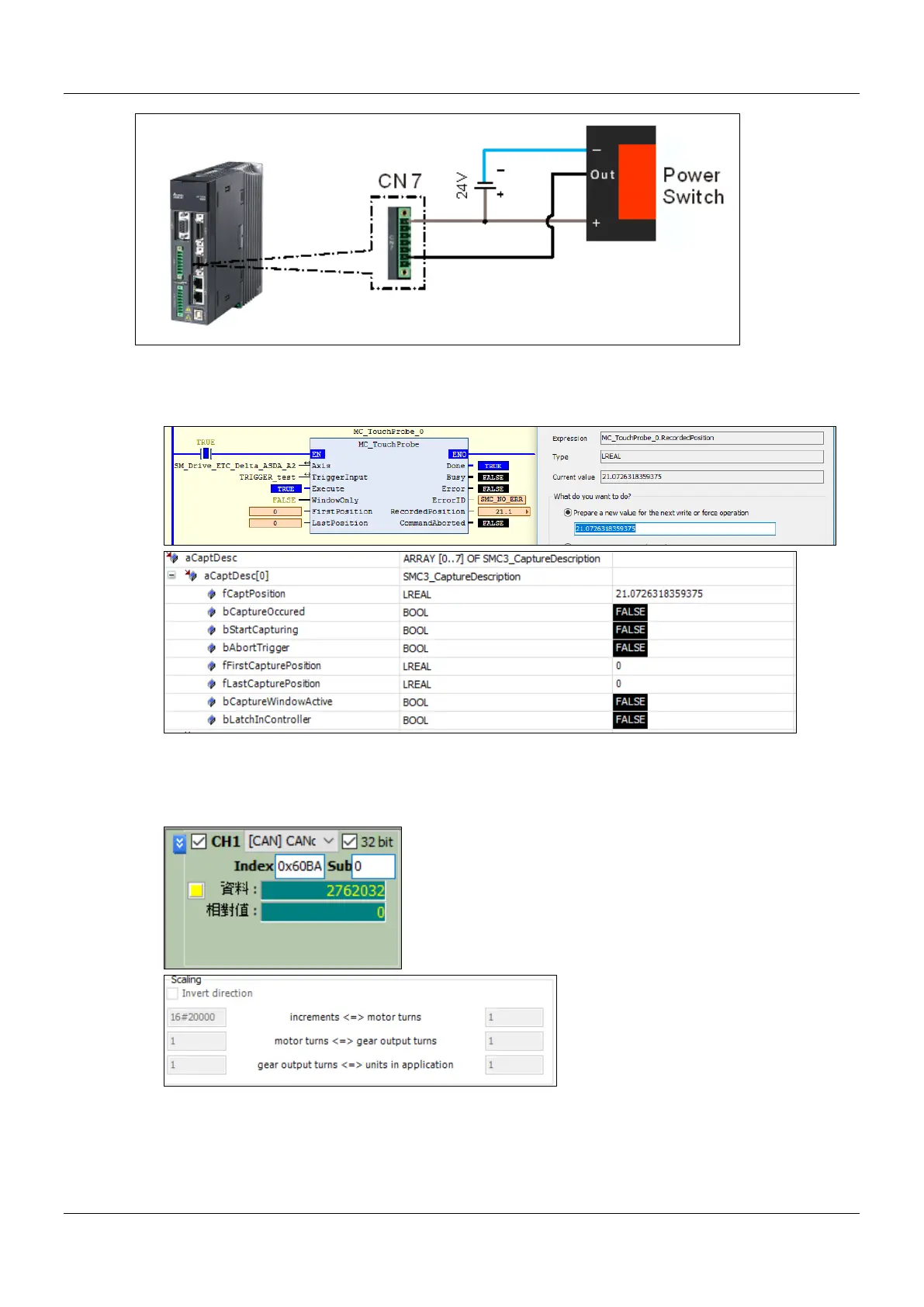
Trigger signal is from DI13 of CNY extension DI connector. You can start the configuration with the diagram above.
Trigger channel must be specified by the function block. The following example demonstrates with rising edge
trigger.
When the signal on DI13 of the servo is triggered, MC_TouchProbeOutputsDone will be True. At the same time,
MC_TouchProbe reads the value stored in the object 0x60BA(Touch Probe Pos1 Pos Value). After being converted
with the gear ratio, the value will be stored in the axis parameter fCaptPosition, which will be output by
RecordedPosition.
As a result of the gear ratio being set to 0x20000: 1, when the drive is rising edge triggered, the value in 0x60BA
must be divided with 0x20000. The signal is triggered by the 2762032 index pulses; therefore, the position is
recorded at 21.0726318359375(2762032/131072).
 Loading...

