AX-Series Motion Controller Instructions Manual Chapter 2
401
2.3.3 Positioning Axis Instructions
The function blocks in this section come from the function library DL_MotionControlLight. The drive handles the main motion curve
planning and calculation of function blocks. So select the positioning axis when setting the axis. Refer to section 7.4 in AX-3 Series
Operation Manual for related settings on a positioning axis.
Positioning axis speed range introduction
The positioning axis speed range is related to the speed range in the EtherCAT servo drive. Tak e the A2-E servo as an
example. The servo drive speed unit is rpm, and the acceleration and deceleration time unit is ms.
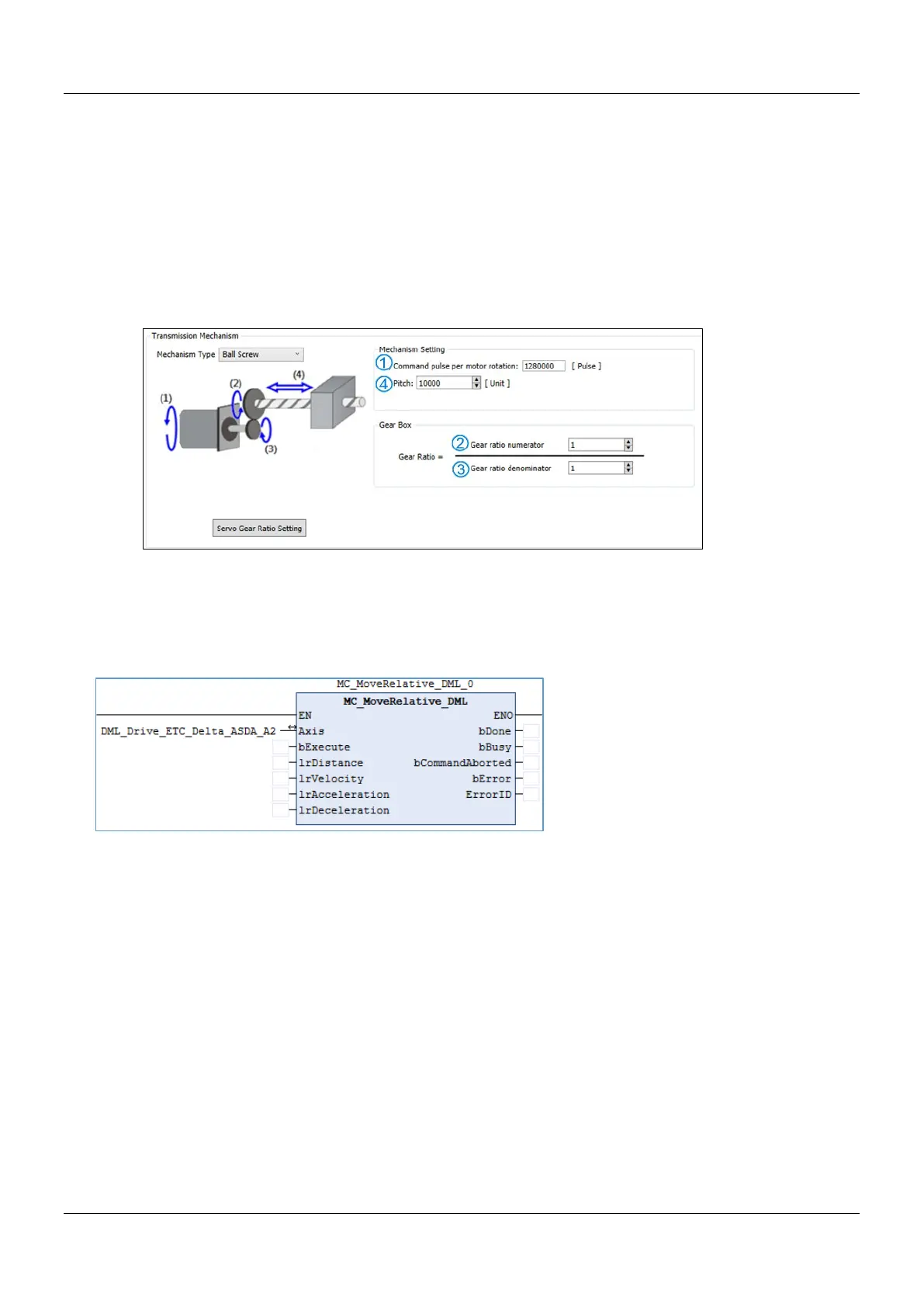
Gear ratio of the DIA-AX software end
Take the above figure as a calculation example
Factor =(
/ )*( / )
The maximum speed and maximum acceleration and deceleration range of the function block are calculated as follows:
Max. lrVelocity
= allowable rated rpm of servo drive / 60 * servo motor one-round resolution / Factor
Max. lrAcceleration
= speed time allowable range / fastest acceleration time for the servo drive
Max. lrDeceleration
= speed time allowable range / fastest deceleration time for the servo drive
Example:
If
- A2-E servo drive allowable rated speed is 3,000 rpm
- A2-E servo motor one-round resolution is 1,280,000 (P1-44 = 1, P1-45 = 1)
- The fastest acceleration and deceleration time is 1 ms for EtherCAT OD 0x6083 and 0x6084
- DIA-AX Factor = 128, then
Max. lrVelocity = 3000/60*128000/128 = 500000 unit/s
Max. lrAcceleration = Max. lrDeceleration = 500000 / (1/1000) = 500000000 unit/s2
*Note: When the conversion unit exceeds the pulse unit, it will run at the maximum allowable pulse unit of the drive.
 Loading...

